Do you have a question about the Sony HCD-ZX10D and is the answer not in the manual?
Technical specifications for the HCD-ZX10D DVD deck receiver, covering various sections and components.
Details power output, sensitivity, and impedance for amplifier inputs and outputs.
Covers system description, laser specifications, and frequency response for the disc player.
Lists models with similar mechanisms and tape transport types.
Provides power requirements, power consumption, dimensions, and mass for the unit.
Details specifications for the tape deck and the FM/AM tuner sections.
Notes on chip component replacement and flexible circuit board repair during servicing.
Lists the formats and disc logos of discs that can be played back on the system.
Explains DVD region code playback, unsupported discs, and multi-session disc cautions.
Alerts users about potential playback issues with music discs using copyright protection technologies.
Contains important notes for servicing, including handling optical pick-up blocks and unleaded solder.
Details the step-by-step disassembly process for various sections of the unit.
Explains various test modes used for checking system functions and diagnostics.
Lists block diagrams and schematic diagrams for different sections of the unit.
Precautions for handling the optical pick-up block, flexible boards, and laser diode emission checks.
Information on unleaded solder characteristics and releasing the disc tray lock.
Instructions for initializing memory after replacing the DMB07 board to ensure proper function.
Defines pass/fail criteria for the optical pick-up block and shows RF signal waveforms for CD/DVD.
Details oscilloscope connection setup and checking locations on the DMB07 board.
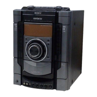
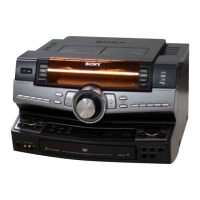
Identifies controls on the main unit and symbols used on the remote control and unit.
Step-by-step instructions for setting and adjusting the system's clock using the remote control.
Provides a flowchart illustrating the order of disassembly for the set's sections.
Details steps for removing the cover, case, loading panel, and front panel sections.
Procedure for removing the top cover, including screw details.
Procedure for removing the main case, specifying screw types and locations.
Steps for removing the loading panel and disc tray, involving gear rotation.
Details disassembly of the front panel, including screws, connectors, and wires.
Steps for removing the back panel, including screws, wires, and connectors.
Procedure for removing the main board, specifying wire and connector disconnections.
Steps for removing the bracket (TR) block and DVD mechanism deck, involving gears and screws.
Specific steps for removing the DVD mechanism deck, including gear rotation and screw removal.
Procedure for removing the optical traverse unit, including chuck assembly.
Steps for removing the RF board, specifying cable and screw disconnections.
Procedure for removing the tape mechanism deck, including wire and screw removal.
Explains GC Test Mode for system checks and MC Test Mode for section tests.
Details tape function checks and AMS test mode procedures for tape decks.
Procedures for Cold Reset, VACS ON/OFF, and AM Step Change functions.
Explains CD Tray Lock Mode, Video/Sat Switching, and DVD Color System Switching.
Details DVD Progressive format switching and DVD Ship Modes for service.
Describes DVD Power Manage function and disabling the repeat limit.
General description and starting procedure for the DVD Test Mode.
Details on operating Syscon Diagnosis, including check menus and error handling.
Explains general checking methods and lists testable items.
Details on checking version info, EEPROM data, and GP I/O signals.
Procedures for SD bus check, video check, and drive auto adjustment.
Detailed steps for adjusting the DVD single layer disc, covering servo and track adjustments.
Detailed steps for adjusting the CD disc, including sled tilt, focus servo, and tracking.
Detailed steps for adjusting the DVD dual layer disc, covering Layer 1 and Layer 0 adjustments.
Explains the Drive Manual Operation menu for servo control and adjustments.
Options for selecting disc types, including auto check, DVD, CD, and Hybrid.
Details the information displayed when the system automatically judges the disc type.
Settings for DVD, CD, and Hybrid disc types, including servo control.
Procedures for track/layer jumps and adjustments not writing to EEPROM.
Adjustments that write data to EEPROM, covering focus, tracking, and EQ.
Displays EEPROM data screens for checking current servo adjustments.
Screens for checking disc memory and displaying error rates (PI1, PI2, PO).
Procedures for SACD water mark check and mechanism deck aging test.
Displays servo emergency history, error codes, and clearing procedures.
Displays mechanism deck error history, including operating status at time of error.
Displays ROM version and region code for system controllers.
Describes the process for adjusting video levels to meet NTSC standards using color bars.
Precautions for adjustments and torque measurement specifications for the tape deck.
Procedure for adjusting the record/playback head azimuth for both decks.
Criteria for determining pass or fail of the optical pick-up block, referencing SERVICING NOTES.
Precautions for DVD block adjustment and auto servo adjustment procedures.
Explains the purpose and procedure for checking video levels for correct brightness.
Block diagram illustrating the RF servo section, showing signal paths and components.
Block diagram for the video and changer sections, detailing data buses and signal paths.
Block diagram showing the tuner and tape sections, including muting and AMS circuits.
Block diagram of the audio section, illustrating signal paths from inputs to outputs.
Block diagram of the amplifier section, showing power stages and protection circuits.
Block diagram of the panel and power supply sections, illustrating voltage regulation and control signals.
Printed wiring board layout for the RF board, showing component placement on both sides.
Schematic diagram for the RF board, detailing components and their connections.
Printed wiring board layout for the DMB07 board (component side), showing ICs and components.
Printed wiring board layout for the DMB07 board (conductor side), showing component placement.
Schematic diagram for the DMB07 board, part 1/8, showing ICs and connections.
Schematic diagram for the DMB07 board, part 2/8, detailing ICs and their interconnections.
Schematic diagram for the DMB07 board, part 3/8, illustrating driver ICs and connections.
Schematic diagram for the DMB07 board, part 4/8, showing memory and controller ICs.
Schematic diagram for the DMB07 board, part 5/8, detailing latch ICs and bus connections.
Schematic diagram for the DMB07 board, part 6/8, showing DVD system processor connections.
Schematic diagram for the DMB07 board, part 7/8, illustrating SD-RAM and interface ICs.
Schematic diagram for the DMB07 board, part 8/8, showing D/A converters and regulators.
Printed wiring board layout for the video board, showing connectors and components.
Schematic diagram for the video board, detailing video switching drivers and amplifiers.
Printed wiring board layouts for the changer section, including MD-94 and SE-130 boards.
Schematic diagram for the changer section, showing disc detection and motor control signals.
Printed wiring board layout for the main board, showing component placement.
Schematic diagram for the main board, part 1/5, illustrating power and tuner circuits.
Schematic diagram for the main board, part 2/5, showing processor and voltage regulator circuits.
Schematic diagram for the main board, part 3/5, detailing audio amplifier and volume control circuits.
Schematic diagram for the main board, part 4/5, showing power supply and relay control circuits.
Schematic diagram for the main board, part 5/5, illustrating amplifier output and protection circuits.
Printed wiring board layout for the front amp section, showing power board components.
Schematic diagram for the front amp section, part 1/2, showing amplifier IC and protection circuits.
Schematic diagram for the front amp section, part 2/2, detailing speaker output stages and connections.
Printed wiring board layout for the surround board, showing IC and component placement.
Schematic diagram for the surround board, illustrating amplifier IC and output stages.
Printed wiring board layout for the panel section (1/5), covering MIC and GAME/HP boards.
Schematic diagram for the panel section (1/5), showing MIC amplifier and echo circuits.
Printed wiring board layout for the panel section (2/5), showing display controller and switches.
Schematic diagram for the panel section (2/5), detailing the display controller and front panel interface.
Printed wiring board layout for the panel section (3/5), covering VOL and CURSOR boards.
Schematic diagram for the panel section (3/5), illustrating volume and button control circuits.
Printed wiring board layout for the panel section (4/5), covering CD-L, TC-A, and JOG boards.
Schematic diagram for the panel section (4/5), showing switch and encoder circuits.
Printed wiring board layout for the panel section (5/5), covering TC-B, CD-R, and FUNCTION SW boards.
Schematic diagram for the panel section (5/5), detailing LED and switch circuits for various functions.
Printed wiring board layouts for the power supply section, including TRANS and VOLTAGE SELECTOR boards.
Schematic diagram for the power supply section, showing transformer and regulator circuits.
Waveforms for various test points in RF, DMB07, VIDEO, MAIN, and PANEL sections.
Block diagrams for key ICs, illustrating their internal functions and pin configurations.
Details pin functions for IC207 (DVD System Processor) on the DMB07 board.
Continuation of pin function details for IC207, covering VDAC signals and system clocks.
Further pin function details for IC207, covering interface and control signals.
Details pin functions for IC701, the DVD Decoder on the DMB07 board, covering data and control signals.
Details pin functions for IC901, the Master Controller on the MAIN board, covering various control signals.
Continuation of pin functions for IC701 (DVD Decoder), covering data buses and system signals.
Further pin functions for IC701 (DVD Decoder), including servo control and analog interface signals.
Additional pin functions for IC701 (DVD Decoder), covering subcode and clock signals.
Details pin functions for IC901, the Mechanism Controller on the DMB07 board, covering servo and control signals.
Continuation of pin functions for IC901 (Mechanism Controller), including tape mechanism and tuner control signals.
Details pin functions for IC401, the Master Controller on the MAIN board, covering various control and interface signals.
Continuation of pin functions for IC401 (Master Controller), covering audio, video, and muting control signals.
Further pin functions for IC401 (Master Controller), relating to tuner and tape mechanism control.
Details pin functions for IC901, the Display Controller on the PANEL board, covering grid drive and LED outputs.
Exploded view of the unit's case section, showing major external components.
Exploded view of the panel board section, detailing front panel controls and related boards.
Exploded view of the front panel section, showing buttons, knobs, and associated parts.
Exploded view of the back panel section, detailing components like the DVD mechanism and power board.
Exploded view of the heat sink section, showing associated boards and fuses.
Exploded view of the chassis section, identifying core structural components and boards.
Exploded views of the DVD mechanism deck, showing tray, gears, chuck assembly, and motors.
Exploded view of the optical block section, showing the RF board and optical traverse unit.
Lists parts for the CD-L and CD-R boards, including connectors, resistors, switches, LEDs, transistors, and capacitors.
Lists parts for the cursor board, including resistors and switches.
Lists ceramic and electrolytic chip capacitors for the DMB07 board with their specifications.
Lists capacitors, connectors, diodes, and filters for the DMB07 board with specifications.
Lists transistors used on the DMB07 board with their part numbers and types.
Lists resistors for the DMB07 board with their values, tolerance, and wattage.
Continues the list of resistors for the DMB07 board, including short chips and specific types.
Continues the list of resistors for the DMB07 board, including short chips and specific types.
Continues the list of resistors for the DMB07 board, including various values and remarks.
Lists tactile switches used on the DMB07 board for various functions.
Lists parts for GAME/HP, JOG, MAIN, POWER, and VOL boards, including resistors and capacitors.
Continues the list of capacitors for the DMB07 board, detailing types, values, tolerance, and voltage ratings.
Continues the list of capacitors for the DMB07 board, detailing types, values, tolerance, and voltage ratings.
Lists various components for the DMB07 board, including connectors, diodes, ICs, coils, transistors, and resistors.
Lists parts for the RF, SE-130, and SENSOR boards, including capacitors, connectors, and diodes.
Continues the list of transistors for the DMB07 board with part numbers and types.
Continues the list of resistors for the DMB07 board with values, tolerance, and wattage.
Continues the list of resistors for the DMB07 board, including short chips and specific types.
Continues the list of resistors for the DMB07 board, including various values and tolerances.
Continues the list of resistors for the DMB07 board, including various values, tolerances, and remarks.
Continues the list of resistors for the DMB07 board, including short chips and specific types.
Lists tactile switches used on the DMB07 board for various functions.
Lists parts for the MD-94, MIC, and VOL boards, including resistors and capacitors.
Lists parts for the PANEL board, including capacitors, connectors, diodes, transistors, and resistors.
Lists parts for the TC-A board, including transistors, resistors, and switches.
Lists parts for the TRANS board, including connectors and diodes.
Lists parts for the VIDEO board, including capacitors and connectors.
Lists parts for the POWER board, including resistors, capacitors, and switches.
Lists parts for the VOLTAGE SELECTOR board, including switches, capacitors, and connectors.
Lists parts for the SURROUND board, including diodes, ICs, coils, transistors, resistors, relays, and connectors.
Lists resistors for the DMB07 board, including various values, tolerance, and wattage.
Continues the list of resistors for the DMB07 board, detailing values, tolerance, and remarks.
Lists parts for the RF, SE-130, and SENSOR boards, including capacitors, connectors, and diodes.
Lists parts for the TC-A board, including diodes, transistors, resistors, and switches.
Lists parts for the TRANS board, including transistors and resistors.
Lists LEDs, shorts, transistors, resistors, and switches for the TC-A board.
Lists parts for the TC-B and TRANS boards, including connectors and capacitors.
Lists parts for the VIDEO board, including capacitors and connectors.
Lists capacitors, connectors, and short/ferrite bead components for the VIDEO board.
Lists ICs, jacks, terminals, transistors, and resistors for the VIDEO board.
Lists parts for the VOL board, including resistors and switches.
Continues the list of resistors for the VOL board, specifying values and tolerance.
Lists switches used on the VOL board for various functions.
Lists parts for the VOLTAGE SELECTOR board, including switches, capacitors, and connectors.
Lists miscellaneous items like wires, mechanical parts, fans, adapters, and transformers.
Records revision information, including version, date, and description of changes.