EasyManua.ls Logo

Sony HCD-ZX70DVD User Manual

Sony HCD-ZX70DVD
136 pages
To Next Page IconTo Next Page
Page #1 background imageLoading...
Page #1 background image
SERVICE MANUAL
Amplifier section
AUDIO POWER SPECIFICATIONS:
(U.S.A. model only)
POWER OUTPUT AND TOTAL HARMONIC
DISTORTION:
with 8 ohm loads both channels driven, from 120-
10,000 Hz; rates 90 watts per channel minimum RMS
power, with no more than 10% total harmonic
distortion from 250 milliwatts to rated output.
Total harmonics distortion
Less than 0.07%
(8 ohms at 1 kHz, 50 W)
Center Speaker:
Continuous RMS power output
40 watts
(8 ohms at 1 kHz,
10% THD)
Rear Speaker:
Continuous RMS power output
40 + 40 watts
(8 ohms at 1 kHz,
10% THD)
Canadian model:
Front Speaker:
Continuous RMS power output
100 + 100 watts
(8 ohms at 1 kHz,
10% THD)
Total harmonics distortion
Less than 0.07%
(8 ohms at 1 kHz, 50 W)
Center Speaker:
Continuous RMS power output
40 watts
(8 ohms at 1 kHz,
10% THD)
Rear Speaker:
Continuous RMS power output
40 + 40 watts
(8 ohms at 1 kHz,
10% THD)
European model:
Front Speaker:
DIN power output (rated) 80 + 80 watts
(8 ohms at 1 kHz, DIN)
Continuous RMS power output (reference)
100 + 100 watts
(8 ohms at 1 kHz,
10% THD)
Music power output (reference)
170 + 170 watts
(8 ohms at 1 kHz,
10% THD)
Center Speaker:
DIN power output (rated) 30 watts
(8 ohms at 1 kHz, DIN)
Continuous RMS power output (reference)
40 watts
(8 ohms at 1 kHz,
10% THD)
Music power output (reference)
60 watts
(8 ohms at 1 kHz,
10% THD)
COMPACT DISC DECK RECEIVER
SPECIFICATIONS
HCD-ZX70DVD
US Model
Canadian Model
AEP Model
UK Model
E Model
Australian Model
Chinese Model
HCD-ZX70DVD is the Amplifier, DVD/CD
player, Tape Deck and Tuner section in
MHC-ZX70DVD.
– Continued on next page –
Model Name Using Similar Mechanism NEW
DVD
DVD Mechanism Type CDM53J-DVBU1
Section
Base Unit Name DVBU1
Optical Pick-up Name KHM-220AAA
TAPE
Model Name Using Similar Mechanism HCD-ZX30AV
Section
Tape Transport Mechanism Type TCM-230AWR12
This stereo system is equipped with the Dolby B-type noise
reduction system*.
* Manufactured under license from Dolby Laboratories
Licensing Corporation.
DOLBY and the double-D symbol ; are trademarks of
Dolby Laboratories Licensing Corporation.
This system incorporates Dolby
*
Digital and Pro Logic
Surround.
* Manufactured under license from Dolby Laboratories.
“Dolby”, “AC-3”, “Pro Logic” and the double-D symbol ;
are trademarks of Dolby Laboratories.
Confidential unpublished Works. © 1992-1997 Dolby
Laboratories, Inc. All rights reserved.
9-929-264-15 Sony Corporation
2004I05-1 Audio Group
© 2004.09 Published by Sony Engineering Corporation
Ver 1.4 2004.09

Table of Contents

Question and Answer IconNeed help?

Do you have a question about the Sony HCD-ZX70DVD and is the answer not in the manual?

Sony HCD-ZX70DVD Specifications

General IconGeneral
Disc PlaybackDVD, CD, CD-R/RW
TunerFM/AM
Remote ControlYes
ConnectivityUSB
FunctionsCD
Audio FormatsMP3
InputsAUX
OutputsHeadphone Out
TypeMini Hi-Fi System

Summary

Service Manual

Audio Power Specifications

Details audio power output and total harmonic distortion for various models.

Specifications

Lists general specifications including mechanism and model names.

Servicing Notes

Notes on Handling Optical Pick-up

Precautions for handling the optical pick-up block.

Notes on Laser Diode Emission Check

Guidelines for checking laser diode emission safely.

Safety Check-out and Tests

Safety Check-out

Procedures for performing safety checks after service.

Leakage Test

Details the AC leakage test procedure and limits.

Caution: Laser Radiation

Warning about hazardous radiation exposure from laser.

General Information

Location of Controls

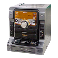
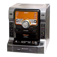
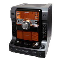
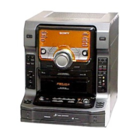
Identifies controls on the front view of the unit.

Disassembly Procedures

Upper Case Disassembly

Details the procedure for removing the upper case.

Front Panel Section Disassembly

Details the procedure for removing the front panel section.

Back Panel Section Disassembly

Details the procedure for removing the back panel section.

Main Board Access

Details the procedure for accessing the main board.

Power Transformer Removal

Details the procedure for removing the power transformer.

IF Board Access

Details the procedure for accessing the IF board.

Front Amp Board Access

Details the procedure for accessing the front amplifier board.

MB Board Access

Details the procedure for accessing the MB board.

DVD Mechanism Deck Removal

Details the procedure for removing the DVD mechanism deck.

Base, Bracket, and Magnet Assembly Removal

Details the procedure for removing base, bracket, and magnet assembly.

Magnet Assembly and DVD Base Unit Removal

Details the procedure for removing magnet assembly and DVD base unit.

Optical Pick-up and TK Board Removal

Details the procedure for removing optical pick-up and TK board.

Sub Tray Removal

Details the procedure for removing the sub tray.

Chassis, Stocker, and Slider Removal

Details the procedure for removing chassis, stocker, and slider.

Tape Mechanism Deck Removal

Details the procedure for removing the tape mechanism deck.

Cable Setting

Instructions for connecting the cable from the panel board to the CD board.

Assembly Procedures

Gears Installation

Details the steps for installing gears.

Slider (Selection) Installation

Details the steps for installing the slider (selection).

Stocker Section Installation

Details the steps for installing the stocker section.

Chassis (Mold B) Section Installation

Details the steps for installing the chassis (mold B) section.

Mechanical Adjustments

Torque Measurement

Provides torque specifications for various adjustments.

Diagrams and Schematics

Notes for Printed Wiring Boards and Schematic Diagrams

Provides important notes and conventions for diagrams.

Circuit Boards Location

Shows the physical location of various circuit boards within the unit.

Printed Wiring Board – TK Board

Shows the printed wiring board layout for the TK board.

Schematic Diagram – TK Board

Provides the schematic diagram for the TK board.

Printed Wiring Board – MB Board (Side A)

Shows the printed wiring board layout for the MB board (Side A).

Printed Wiring Board – MB Board (Side B)

Shows the printed wiring board layout for the MB board (Side B).

Schematic Diagram – MB Board (1/10)

Provides schematic diagram for the MB board (1/10).

Schematic Diagram – MB Board (2/10)

Provides schematic diagram for the MB board (2/10).

Schematic Diagram – MB Board (3/10)

Provides schematic diagram for the MB board (3/10).

Schematic Diagram – MB Board (4/10)

Provides schematic diagram for the MB board (4/10).

Schematic Diagram – MB Board (5/10)

Provides schematic diagram for the MB board (5/10).

Schematic Diagram – MB Board (6/10)

Provides schematic diagram for the MB board (6/10).

Schematic Diagram – MB Board (7/10)

Provides schematic diagram for the MB board (7/10).

Schematic Diagram – MB Board (8/10)

Provides schematic diagram for the MB board (8/10).

Schematic Diagram – MB Board (9/10)

Provides schematic diagram for the MB board (9/10).

Schematic Diagram – MB Board (10/10)

Provides schematic diagram for the MB board (10/10).

Printed Wiring Board – IF Board

Shows the printed wiring board layout for the IF board.

Schematic Diagram – IF Board

Provides the schematic diagram for the IF board.

Printed Wiring Boards – CDM Section

Shows printed wiring boards for the CDM section.

Schematic Diagram – CDM Section

Provides schematic diagrams for the CDM section.

Printed Wiring Board – AUDIO Board

Shows the printed wiring board layout for the AUDIO board.

Schematic Diagram – AUDIO Board

Provides the schematic diagram for the AUDIO board.

Printed Wiring Board – LEAF SW Board

Shows the printed wiring board layout for the LEAF SW board.

Schematic Diagram – LEAF SW Board

Provides the schematic diagram for the LEAF SW board.

Printed Wiring Board – MAIN Board

Shows the printed wiring board layout for the MAIN board.

Schematic Diagram – MAIN Board (1/5)

Provides schematic diagram for the MAIN board (1/5).

Schematic Diagram – MAIN Board (2/5)

Provides schematic diagram for the MAIN board (2/5).

Schematic Diagram – MAIN Board (3/5)

Provides schematic diagram for the MAIN board (3/5).

Schematic Diagram – MAIN Board (4/5)

Provides schematic diagram for the MAIN board (4/5).

Schematic Diagram – MAIN Board (5/5)

Provides schematic diagram for the MAIN board (5/5).

Printed Wiring Board – MIC Board

Shows the printed wiring board layout for the MIC board.

Schematic Diagram – MIC Board

Provides the schematic diagram for the MIC board.

Printed Wiring Boards – FRONT AMP/HP Boards

Shows printed wiring boards for the FRONT AMP/HP sections.

Schematic Diagram – FRONT AMP/HP Boards

Provides schematic diagrams for the FRONT AMP/HP sections.

Printed Wiring Board – SURR AMP Board

Shows the printed wiring board layout for the SURR AMP board.

Schematic Diagram – SURR AMP Board

Provides the schematic diagram for the SURR AMP board.

Printed Wiring Boards – PANEL/CD SW Boards

Shows printed wiring boards for PANEL and CD SW sections.

Schematic Diagram – PANEL/CD SW Boards

Provides schematic diagrams for PANEL and CD SW sections.

Printed Wiring Board – SUB PANEL Board

Shows the printed wiring board layout for the SUB PANEL board.

Schematic Diagram – SUB PANEL Board

Provides the schematic diagram for the SUB PANEL board.

Printed Wiring Boards – TRANS/SUB TRANS Boards

Shows printed wiring boards for TRANS and SUB TRANS sections.

Schematic Diagram – TRANS/SUB TRANS Boards

Provides schematic diagrams for TRANS and SUB TRANS sections.

IC Block Diagrams and Waveforms

IC Block Diagrams

Illustrates internal block structures of key IC components.

Waveforms

Displays various waveforms for troubleshooting and analysis.

Exploded Views

Case Exploded View

Exploded view of the unit's outer case and related parts.

Front Panel Section Exploded View

Exploded view of the front panel section and its components.

Chassis Section Exploded View

Exploded view of the main chassis and its mounted components.

DVD Mechanism Deck Section-1 Exploded View

Exploded view of the DVD mechanism deck (part 1).

DVD Mechanism Deck Section-2 Exploded View

Exploded view of the DVD mechanism deck (part 2).

Tape Mechanism Deck Section-1 Exploded View

Exploded view of the tape mechanism deck (part 1).

Tape Mechanism Deck Section-2 Exploded View

Exploded view of the tape mechanism deck (part 2).

Electrical Parts List

Audio Section Parts

Lists capacitor, connector, IC, coil, transistor, resistor parts.

Audio, CD SW, Clamp Motor, Connector Parts

Lists parts for AUDIO, CD SW, CLAMP MOTOR, and CONNECTOR.

Front Amp Section Parts

Lists electrical parts for the FRONT AMP section.

Front Amp, HP Section Parts

Lists electrical parts for FRONT AMP and HP sections.

Front Amp, HP, IF Section Parts

Lists electrical parts for FRONT AMP, HP, and IF sections.

IF, Init/Count SW, In SW, Leaf SW Section Parts

Lists electrical parts for IF, INIT/COUNT SW, IN SW, LEAF SW sections.

Leaf SW, Load Motor, Main Section Parts

Lists electrical parts for LEAF SW, LOAD MOTOR, and MAIN sections.

Main Section Parts

Lists electrical parts for the MAIN section.

Main Section Parts List (Continued)

Lists electrical parts for the MAIN section.

Main Section Parts List (More)

Lists electrical parts for the MAIN section.

Main Section Parts List (Transistors & Resistors)

Lists transistor and resistor components for the MAIN section.

Main Section Resistor List

Lists resistor components for the MAIN section.

Main Section Resistor List (Continued)

Lists resistor components for the MAIN section.

Main Section Resistor and Other Parts List

Lists resistor, variable resistor, and vibrator components.

MB Section Capacitor Parts

Lists capacitor components for the MB section.

MB Section Connector, Diode, Ferrite Bead, Filter Parts

Lists connector, diode, ferrite bead, and filter components.

MB Section Capacitor Parts List

Lists capacitor components for the MB section.

MB Section Transistor and Resistor Parts

Lists transistor and resistor components for the MB section.

MB, MIC Section Parts

Lists transistor, resistor, relay, thermistor, capacitor parts.

Panel, Sensor, Sub Panel Section Parts

Lists switch, vibrator, capacitor, LED, resistor, transistor parts.

Panel Section Parts

Lists transistor and resistor components for the PANEL section.

Panel, Sensor, Sub Panel Section Parts List

Lists switch, vibrator, capacitor, diode, photo transistor parts.

Sub Panel, Sensor, Surr Amp Section Parts

Lists capacitor, diode, switch components for SUB PANEL, SURR AMP.

Surr Amp, TK Section Parts

Lists earth terminal, IC, transistor, resistor, relay, thermistor parts.

TK and Trans Section Parts

Lists connector, diode, resistor, switch, transformer components.

Miscellaneous Parts

Lists wire, power block, transformer, and screw parts.

Hardware List

Lists various screws and hardware components.

Service Manual Supplement

Correction of Schematic Diagrams

Indicates corrected portions in schematic diagrams.

Servicing Notes

Provides notes on servicing procedures like CDM SHIP MODE.

Service Modes

Explains various service modes (MC Cold/Hot Reset, CD Service Mode).

Test Mode Procedures

Details how to access and use test modes for diagnosis and adjustment.

Electrical Adjustments

Details procedures for electrical adjustments like head azimuth.

Block Diagrams

Contains block diagrams illustrating signal flow for various sections.

IC Block Diagrams

Shows block diagrams for key ICs.

IC Pin Function Descriptions

Details pin functions for specified ICs.

Revision History

Related product manuals