EasyManua.ls Logo

Sony HCD-CL1 User Manual

Sony HCD-CL1
70 pages
To Next Page IconTo Next Page
Page #1 background imageLoading...
Page #1 background image
CHC-CL1/CL3
US Model
Australian Model
CHC-CL1
AEP Model
UK Model
E Model
CHC-CL1/CL3
SERVICE MANUAL
COMPACT Hi-Fi COMPONENT SYSTEM
Sony Corporation
Audio Entertainment Group
General Engineering Dept.
Ver 1.0 2001. 03
9-873-859-11
2001C1600-1
© 2001.3
COMPONENT MODEL NAME
CHC-CL1/CL3 are composed of following models.
As for the service manual, it is issued for each component model,
then, please refer to them.
PARTS LIST
Part No. Description Remark
ACCESSORIES & PACKING MATERIALS
********************************
1-476-443-11 COMMANDER, STANDARD (RM-SCL1)
1-501-374-11 ANTENNA, LOOP (AM)
1-501-659-41 ANTENNA (FM) (CL1:US,AUS,E,MX,TW,KR/CL3:MX,KR)
1-501-804-11 ANTENNA (FM) (CL1:AEP,UK/CL3:AEP,UK)
4-210-254-01 CUSHION (FOOT)
4-228-952-01 COVER,BATTERY (FOR RM-SCL1)
4-233-430-11 MANUAL, INSTRUCTION
(CL1:US,AEP,UK,AUS,E,TW/CL3:AEP,UK) (ENGLISH)
4-233-430-21 MANUAL, INSTRUCTION (CL1:AEP/CL3:AEP) (FRENCH)
4-233-430-31 MANUAL, INSTRUCTION (CL1:AEP,E,MX/CL3:AEP,MX)
(SPANISH)
4-233-430-41 MANUAL, INSTRUCTION (CL1:AEP/CL3:AEP)
(GERMAN, DUTCH, ITALIAN)
4-233-430-51 MANUAL, INSTRUCTION (CL1:AEP/CL3:AEP)
(SWEDISH, POLISH)
4-233-430-61 MANUAL, INSTRUCTION (CL1:AEP/CL3:AEP) (PORTUGUESE)
4-233-430-71 MANUAL, INSTRUCTION (CL1:AEP/CL3:AEP)
(DANISH, FINNISH)
4-233-430-81 MANUAL, INSTRUCTION (CL1:AEP/CL3:AEP) (RUSSIAN)
4-233-430-91 MANUAL, INSTRUCTION (CL1:TW) (CHINESE)
4-233-431-11 MANUAL, INSTRUCTION (CL1:KR/CL3:KR) (KOREAN)
Abbreviation
MX : Mexican model
AUS : Australian model
KR : Korea model
TW : Taiwan model
SPECIFICATIONS
General
Power requirements
U.S.A. model: 120 V AC, 60 Hz
AEP models: 230 V AC, 50/60 Hz
Australian and New Zealand models:
230 240 V AC, 50/
60 Hz
Mexican model: 120 V AC, 60 Hz
Korean model: 220 V AC, 60 Hz
Other models: 120 V, 220 V, 230
240 V AC, 50/60 Hz
Adjustable with voltage
selector
Power consumption
U.S.A. model:
CHC-CL1: 100 watts
AEP models:
CHC-CL3: 165 watts
CHC-CL1: 100 watts
CHC-CL3/CL1: 0.5 watts (at the Power
Saving Mode)
Other models:
CHC-CL3: 165 watts
CHC-CL1: 100 watts
Dimensions (w/h/d) incl. projecting parts and controls
Amplifier/Tuner/Tape/CD section:
Approx. 215 × 285 ×
421 mm
Speaker: Approx. 210 × 285 ×
260 mm
Mass
Amplifier/Tuner/Tape/CD section:
CHC-CL3: Approx. 8.0 kg
CHC-CL1: Approx. 7.7 kg
Speakers: Approx. 3.8 kg net per
speaker
Supplied accessories Remote (1)
R6 (size AA) batteries (2)
AM loop antenna (1)
FM lead antenna (1)
Speaker pads (8)
Design and specifications are subject to change
without notice.
COMPACT DISC DECK
RECEIVER SYSTEM
FRONT SPEAKER
SYSTEM
CHC-CL3
HCD-CL3
SS-SCL3
CHC-CL1
HCD-CL1
SS-SCL1 (SILVER)
SS-SCL1B (BLACK)
Question and Answer IconNeed help?

Do you have a question about the Sony HCD-CL1 and is the answer not in the manual?

Sony HCD-CL1 Specifications

General IconGeneral
Speaker Configuration2-way
TunerFM/AM
BluetoothNo
USB PlaybackNo
Cassette DeckYes
Remote ControlYes
Audio Channels2.0
Disc PlaybackCD
FunctionsCD, Radio

Summary

General Information and Specifications

Component Model Names

Identifies the component models making up the system.

General Specifications

Lists power, consumption, dimensions, and mass of the system.

Parts List

Lists accessory and packing materials included with the unit.

System Overview and Amplifier Specifications

Dolby Noise Reduction System

Explains the Dolby B-type noise reduction system used.

Amplifier Section Specifications

Details audio power output and harmonic distortion for various models.

CD and Tape Deck Specifications

Lists specifications for CD mechanism and tape transport types.

Technical Specifications and Safety Checks

CD Player and Tape Deck Specifications

Provides technical details for CD player and tape deck sections.

Tuner Section Specifications

Lists FM and AM tuning ranges and intermediate frequencies.

General Specifications and Power Requirements

Details power requirements, dimensions, and mass.

Safety Check-out: AC Leakage

Critical procedure to check for AC leakage from exposed metal parts.

Servicing Notes and Precautions

Handling Optical Pick-up and Laser Diode

Precautions for handling sensitive optical pick-up and laser components.

Chip Component Replacement and PCB Repair

Guidelines for replacing chip components and repairing flexible PCBs.

Safety-Related Component Warning

Identifies critical safety components that must be replaced with specified parts.

System Controls and Operation

Front Panel Controls Overview

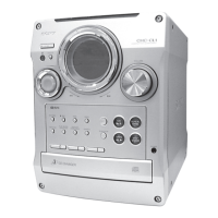
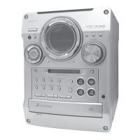
Identifies and labels all controls and indicators on the front panel.

Button Descriptions

Explains the function of each button on the unit and remote.

Basic Setup and Power Saving

Setting the System Time

Step-by-step procedure for setting the system's clock.

Saving Power in Standby Mode

Information on how to activate and cancel power saving features.

Disassembly Procedures

Disassembly Flow Chart

Provides an overview of the sequence for disassembling the unit.

Step 3-1: Top Panel and Side Panels

Detailed instructions for removing the top and side panels.

Component Disassembly

Step 3-2: Cassette Mechanism

Instructions for disassembling the cassette deck assembly.

Step 3-3: Front Panel

Detailed steps for removing and disassembling the front panel.

Internal Component Disassembly

Step 3-4: Panel Board

Instructions for disassembling the panel board assembly.

Step 3-5: Back Panel and Main Board

Steps for removing the back panel and main printed circuit board.

Main Unit Disassembly

Step 3-6: Amp Board and Power Transformer

Instructions for disassembling the amplifier board and power transformer.

Step 3-7: CD Mechanism

Detailed steps for removing the CD mechanism unit.

CD Mechanism Disassembly

Step 3-8: CD Base Unit (BU-30BD60)

Step-by-step instructions for disassembling the CD base unit.

CD Mechanism Sub-component Disassembly

Step 3-9: Driver Board

Instructions for disassembling the driver board.

Step 3-10: Fitting Base and Tray Assy

Steps for removing the fitting base and tray assemblies.

CD Mechanism Mechanical Parts

Step 3-11: Tray Sensor Board

Instructions for disassembling the tray sensor board.

Step 3-12: Slider and Gears

Steps for disassembling the loading slider and associated gears.

CD Mechanism Internal Assemblies

Step 3-13: Stocker Assy, Tray (Sub)

Instructions for disassembling the stocker and sub tray assemblies.

Step 3-14: Disc Sensor Board

Steps for disassembling the disc sensor board.

CD Mechanism Electrical and Motor Parts

Step 3-15: IN OUT SW Board

Instructions for disassembling the IN/OUT switch board.

Step 3-16: Motor Assy and Motor Board

Steps for disassembling the motor assembly and motor board.

Service Test Modes

CD Ship Mode and Service Mode

Procedures for CD ship, memory clear, and service modes.

GC Test Mode

Mode for checking software version, LEDs, and other functions.

MC Test Mode

Mode for testing amplifier, tuner, CD, and tape sections.

CD/TAPE Repeat Limit Release Mode

Mode to disable the 5-time repeat limit for CD/TAPE.

Mechanical and Electrical Adjustments

Torque Measurement Specifications

Table of torque values for mechanical adjustments.

Deck Section Adjustments

General electrical adjustments for the tape deck section.

Head Azimuth and Tape Speed Adjustments

Procedures for adjusting head azimuth and tape speed.

Tape Deck Electrical Adjustments

Record Bias Adjustment Procedure

Steps for adjusting the record bias level.

Tape Speed Check Procedure

Procedure for checking and adjusting tape speed.

CD Player Electrical Adjustments

Record Level Adjustment

Procedure for setting the record input level.

S-Curve Check

Method for checking the CD player's S-curve waveform.

RF Level Check

Procedure for checking the CD player's RF signal level.

CD Player Advanced Checks

E-F Balance (1 Track Jump) Check

Method for checking the E-F balance during CD track jumping.

Diagrams and Circuit Board Layouts

Circuit Boards Location

Identifies the physical location of all printed circuit boards within the unit.

Diagram Notes and Abbreviations

Explains symbols, abbreviations, and notes used in schematic diagrams.

Block Diagrams - CD Section

Optical Pick-up Block Diagram

Block diagram illustrating the optical pick-up component.

IC101 Digital Servo Diagram

Block diagram for the digital servo processor IC.

Block Diagrams - System Control

Syscon Section Block Diagram

Block diagram of the system control (Syscon) section.

Schematic Diagrams - Main Section

Main Section Schematic

Detailed schematic diagram of the main circuit board.

Main Section Schematic (Continued)

Main Section Schematic (Part 2)

Continuation of the main section schematic diagram.

Schematic Diagrams - BD (CD) Section

BD (CD) Section Schematic

Detailed schematic diagram of the BD (CD) circuit board.

Printed Wiring Boards - BD Section

BD (CD) Board Layout

Printed wiring board layout for the CD section.

Schematic Diagrams - Driver Section

Driver Section Schematic

Schematic diagram for the driver circuit section.

Printed Wiring Boards - Driver Section

Driver Section PWB Layout

Printed wiring board layout for the driver section.

Schematic Diagrams - TC Section

TC Section Schematic

Schematic diagram for the TC circuit section.

Printed Wiring Boards - TC Section

TC Board Layout

Printed wiring board layout for the TC section.

Schematic Diagrams - AMP Section

AMP Section Schematic

Detailed schematic diagram of the amplifier circuit board.

Printed Wiring Boards - AMP Section

AMP Board Layout

Printed wiring board layout for the amplifier section.

Schematic Diagrams - Panel Section

Panel Section Schematic

Schematic diagram for the panel interface section.

Printed Wiring Boards - Panel Section

Panel Board PWB Layout

Printed wiring board layout for the panel section.

Schematic Diagrams - Trans Section

Trans Section Schematic

Schematic diagram for the transformer and power supply interface.

Printed Wiring Boards - Trans Section

Trans Board Layout

Printed wiring board layout for the transformer section.

Schematic Diagrams - Power Section

Power Section Schematic

Detailed schematic diagram of the power supply and voltage selector.

Printed Wiring Boards - Power Section

Power Section PWB Layout

Printed wiring board layout for the power supply section.

IC Pin Function Descriptions

IC401 Pin Function Description

Details pin functions for the main control IC (IC401) on the main board.

IC Pin Function Descriptions (Continued)

IC401 Pin Function Description (Part 2)

Continuation of pin function details for the main control IC.

Integrated Circuit Block Diagrams

IC101 Block Diagram (CD)

Block diagram of the CD processor IC (IC101) in the CD section.

IC401 Block Diagram (Main)

Block diagram of the main control IC (IC401) in the main section.

Integrated Circuit Block Diagrams (Continued)

IC701 Block Diagram (Driver)

Block diagram of the driver IC (IC701) on the driver board.

IC302 Block Diagram (TC)

Block diagram of the TC IC (IC302) on the TC board.

Integrated Circuit Block Diagrams (CD Specific)

IC101 Block Diagram (CXD3017Q)

Detailed block diagram of the CD processor IC CXD3017Q.

Integrated Circuit Block Diagrams (Component Specific)

IC201 Block Diagram (Main)

Block diagram of the main audio processor IC (IC201).

IC701 Block Diagram (Driver)

Block diagram of the driver IC (IC701).

IC302 Block Diagram (TC)

Block diagram of the TC IC (IC302).

Exploded Views

Exploded Views Notes

General notes and abbreviations related to exploded views and parts.

Side Panel and Back Panel Assembly

Exploded view illustrating the side panel and back panel assemblies.

Parts List - Side/Back Panel Assembly

Parts for Side/Back Panel Assembly

List of part numbers for the side and back panel assemblies.

Exploded Views - Front Panel

Front Panel Assembly

Exploded view illustrating the front panel assembly.

Exploded Views - Chassis Section

Chassis Assembly

Exploded view illustrating the chassis and associated main boards.

Exploded Views - CD Mechanism (Part 1)

CD Mechanism Deck Assembly (Part 1)

Exploded view of the CD mechanism deck components, part 1.

Exploded Views - CD Mechanism (Part 2)

CD Mechanism Deck Assembly (Part 2)

Exploded view of the CD mechanism deck components, part 2.

Exploded Views - Base Unit

Base Unit (BU-30BD60) Assembly

Exploded view illustrating the BU-30BD60 base unit.

Electrical Parts List - AMP, Back Light, CD

AMP Section Parts List

List of electrical parts for the amplifier section.

Back Light Section Parts List

List of electrical parts for the back light assembly.

BD (CD) Section Parts List

List of electrical parts for the BD (CD) section.

Electrical Parts List - AMP Components

AMP Section Resistors and Transistors

List of resistors and transistors for the amplifier section.

Electrical Parts List - Various Components

AMP Section Capacitors and Relays

List of capacitors and relays for the amplifier section.

Back Light and BD (CD) Section Parts

List of parts for back light and CD sections.

Electrical Parts List - CD and Main Components

BD (CD) Disk Sensor and Driver Parts

List of parts for the CD disk sensor and driver components.

Main Board Components (Resistors, ICs)

List of resistors and ICs for the main board.

Electrical Parts List - Driver and Back Light Components

Main Board Resistors

Additional list of resistors for the main board.

Driver and Back Light Components

List of electrical parts for the driver and back light assemblies.

Electrical Parts List - Main and Interface Components

Main Board Capacitors and Diodes

List of capacitors and diodes for the main board.

Driver, ICs, Jacks, and Jumpers

List of parts for driver ICs, jacks, and jumper resistors.

Electrical Parts List - Main Circuit Components

Main Board Resistors and Transistors

List of resistors and transistors for the main circuit board.

Main Board Coils and Variable Resistors

List of coils and variable resistors for the main board.

Electrical Parts List - Panel, Sub Power, TC Components

Panel and Ring Switch Parts

List of parts for the panel and ring switch boards.

Sub Power and TC Section Parts

List of parts for the sub power and TC boards.

Electrical Parts List - TC, Thermal, and Trans Components

TC, Thermal, and Trans Components

List of parts for the TC, thermal, and trans boards.

Electrical Parts List - Miscellaneous Components

Panel, Sub Power, and TC Capacitors

List of capacitors for the panel, sub power, and TC boards.

Electrical Parts List - Transistor and Fuse Components

Transistor and Fuse Parts

List of transistors and fuses for various sections.

Electrical Parts List - Trans, Tray Sensor, Voltage Selector Components

Trans, Tray Sensor, and Voltage Selector Parts

List of parts for the trans, tray sensor, and voltage selector boards.

Speaker System Specifications

Speaker System Type and Units

Describes the speaker system configuration, including type and units.

Speaker System Exploded Views and Parts

Exploded Views Notes and Abbreviations

General notes and abbreviations for speaker system exploded views.

Speaker System Exploded View (Lch)

Exploded view illustrating the left channel speaker components.

Related product manuals