EasyManua.ls Logo

Sony HCD-CL5MD User Manual

Sony HCD-CL5MD
112 pages
To Next Page IconTo Next Page
Page #1 background imageLoading...
Page #1 background image
HCD-CL5MD
AEP Model
UK Model
E Model
Australian Model
SERVICE MANUAL
MICRO HiFi COMPONENT SYSTEM
Sony Corporation
Audio Entertainment Group
General Engineering Dept.
9-929-583-11
2001B1600-1
© 2001.2
— Continued on next page —
SPECIFICATIONS
Ver 1.0 2001. 02
HCD-CL5MD is the tuner, deck, CD, MD and
amplifier section in CHC-CL5MD.
Model Name Using Similar Mechanism NEW
CD Mechanism Type CDM63B
Base Unit Type BU-30BD61
Optical Pick-up Type A-MAX.3
Model Name Using Similar Mechanism HCD-ZX50MD
MD Mechanism Type MDM-7B
Optical Pick-up Type KMS-260B/K1NP
Model Name Using Similar Mechanism NEW
Tape Transport Mechanism Type TCM-230ASR41CL
CD
SECTION
MD
SECTION
TAPE DECK
SECTION
Amplifier section
AEP model:
DIN power output (Rated):40 + 40 watts
(6 ohms at 1 kHz, DIN)
Continuous RMS power output (Reference):
50 + 50 watts
(6 ohms at 1 kHz, 10%
THD)
Music power output (Reference):
95 + 95 watts
(6 ohms at 1 kHz, 10%
THD)
Other models:
DIN power output (Rated):40 + 40 watts
(6 ohms at 1 kHz, DIN)
Continuous RMS power output (Reference):
50 + 50 watts
(6 ohms at 1 kHz, 10%
THD)
Inputs
VIDEO (AUDIO) IN (phono jacks):
voltage 250 mV,
impedance 47 kilohms
CD DIGITAL IN (Supported sampling frequencies:
32 kHz, 44.1 kHz and 48 kHz)
Outputs
PHONES (stereo minijack):
accepts headphones of
8 ohms or more.
SPEAKER: accepts impedance of 6 to
16 ohms.
CD player section
System Compact disc and digital
audio system
Laser Semiconductor laser
=780 nm)
Emission duration:
continuous
Laser output Max. 44.6 µW*
* This output is the value
measured at a distance
of 200 mm from the
objective lens surface on
the Optical Pick-up
Block with 7 mm
aperture.
Frequency response 20 Hz – 20 kHz (±0.5 dB)

Table of Contents

Question and Answer IconNeed help?

Do you have a question about the Sony HCD-CL5MD and is the answer not in the manual?

Sony HCD-CL5MD Specifications

General IconGeneral
TypeMini Hi-Fi System
MD Player/RecorderYes
TunerFM/AM
Remote ControlYes
Weight (Main Unit)5.5 kg
FunctionsCD, MD, Tuner
Speakers2-Way
Output Power100W

Summary

Specifications

CD Player Specifications

Details of the CD playback mechanism, laser, and frequency response.

Amplifier Specifications

Power output ratings and input impedance for the amplifier section.

MD, Tape Deck, Tuner Specs

Technical details for the MiniDisc, cassette tape, and tuner mechanisms.

General System Specifications

FM/AM tuning ranges, power requirements, and dimensions.

Self-Diagnosis Function

Error Code Descriptions

List of error codes displayed by the system and their meanings.

Error History Display Mode Procedure

Steps to enter and navigate the error history display in test mode.

Automatic Self-Diagnosis Function

Test mode for checking optical pick-up characteristics via auto-diagnosis.

Servicing Notes & Precautions

Optical Pick-Up & Laser Handling

Guidelines for safely handling optical pick-up blocks and laser diodes.

Safety Warnings & Component Replacement

Critical safety warnings for components and replacement procedures.

Jig Usage for Waveform Checks

Information on using special jigs for checking BD (MD) board waveforms.

Disassembly Procedures

Top Panel & Side Panel Disassembly

Step-by-step guide for disassembling the top panel and side panels.

Component Disassembly Steps

Detailed instructions for disassembling various mechanisms and boards.

MD Mechanism Disassembly

Specific steps for disassembling the MD mechanism unit.

CD Mechanism Disassembly

Specific steps for disassembling the CD mechanism unit.

Test Modes & Adjustments

Test Mode Procedures

Instructions for accessing and operating various test modes.

Adjustment Procedures Overview

General guidelines and procedures for mechanical and electrical adjustments.

Specific Adjustment Checks

Detailed procedures for specific adjustments like tape speed and bias.

Laser Diode Emission Checks

Precautions and procedures for checking laser diode emission during adjustment.

Diagrams & Technical Drawings

Circuit Board Locations

Visual guide showing the placement of all circuit boards within the unit.

Schematic & Block Diagrams

Technical diagrams illustrating system architecture and component interconnections.

IC Pin Functions

Detailed pin assignments and functions for key integrated circuits.

Exploded Views, Waveforms & Parts List

Waveform Examples

Illustrations of expected waveforms for different sections of the unit.

Exploded View Sections

Visual breakdowns of major assemblies like panels, mechanisms, and boards.

Electrical Parts List Categories

Categorized list of electronic components with part numbers and specifications.
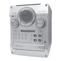
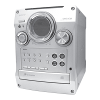
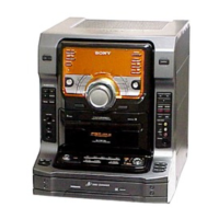
Revision History

Related product manuals