EasyManua.ls Logo

Sony HCD-CL3 User Manual

Sony HCD-CL3
70 pages
To Next Page IconTo Next Page
Page #1 background imageLoading...
Page #1 background image
CHC-CL1/CL3
US Model
Australian Model
CHC-CL1
AEP Model
UK Model
E Model
CHC-CL1/CL3
SERVICE MANUAL
COMPACT Hi-Fi COMPONENT SYSTEM
Sony Corporation
Audio Entertainment Group
General Engineering Dept.
Ver 1.0 2001. 03
9-873-859-11
2001C1600-1
© 2001.3
COMPONENT MODEL NAME
CHC-CL1/CL3 are composed of following models.
As for the service manual, it is issued for each component model,
then, please refer to them.
PARTS LIST
Part No. Description Remark
ACCESSORIES & PACKING MATERIALS
********************************
1-476-443-11 COMMANDER, STANDARD (RM-SCL1)
1-501-374-11 ANTENNA, LOOP (AM)
1-501-659-41 ANTENNA (FM) (CL1:US,AUS,E,MX,TW,KR/CL3:MX,KR)
1-501-804-11 ANTENNA (FM) (CL1:AEP,UK/CL3:AEP,UK)
4-210-254-01 CUSHION (FOOT)
4-228-952-01 COVER,BATTERY (FOR RM-SCL1)
4-233-430-11 MANUAL, INSTRUCTION
(CL1:US,AEP,UK,AUS,E,TW/CL3:AEP,UK) (ENGLISH)
4-233-430-21 MANUAL, INSTRUCTION (CL1:AEP/CL3:AEP) (FRENCH)
4-233-430-31 MANUAL, INSTRUCTION (CL1:AEP,E,MX/CL3:AEP,MX)
(SPANISH)
4-233-430-41 MANUAL, INSTRUCTION (CL1:AEP/CL3:AEP)
(GERMAN, DUTCH, ITALIAN)
4-233-430-51 MANUAL, INSTRUCTION (CL1:AEP/CL3:AEP)
(SWEDISH, POLISH)
4-233-430-61 MANUAL, INSTRUCTION (CL1:AEP/CL3:AEP) (PORTUGUESE)
4-233-430-71 MANUAL, INSTRUCTION (CL1:AEP/CL3:AEP)
(DANISH, FINNISH)
4-233-430-81 MANUAL, INSTRUCTION (CL1:AEP/CL3:AEP) (RUSSIAN)
4-233-430-91 MANUAL, INSTRUCTION (CL1:TW) (CHINESE)
4-233-431-11 MANUAL, INSTRUCTION (CL1:KR/CL3:KR) (KOREAN)
Abbreviation
MX : Mexican model
AUS : Australian model
KR : Korea model
TW : Taiwan model
SPECIFICATIONS
General
Power requirements
U.S.A. model: 120 V AC, 60 Hz
AEP models: 230 V AC, 50/60 Hz
Australian and New Zealand models:
230 240 V AC, 50/
60 Hz
Mexican model: 120 V AC, 60 Hz
Korean model: 220 V AC, 60 Hz
Other models: 120 V, 220 V, 230
240 V AC, 50/60 Hz
Adjustable with voltage
selector
Power consumption
U.S.A. model:
CHC-CL1: 100 watts
AEP models:
CHC-CL3: 165 watts
CHC-CL1: 100 watts
CHC-CL3/CL1: 0.5 watts (at the Power
Saving Mode)
Other models:
CHC-CL3: 165 watts
CHC-CL1: 100 watts
Dimensions (w/h/d) incl. projecting parts and controls
Amplifier/Tuner/Tape/CD section:
Approx. 215 × 285 ×
421 mm
Speaker: Approx. 210 × 285 ×
260 mm
Mass
Amplifier/Tuner/Tape/CD section:
CHC-CL3: Approx. 8.0 kg
CHC-CL1: Approx. 7.7 kg
Speakers: Approx. 3.8 kg net per
speaker
Supplied accessories Remote (1)
R6 (size AA) batteries (2)
AM loop antenna (1)
FM lead antenna (1)
Speaker pads (8)
Design and specifications are subject to change
without notice.
COMPACT DISC DECK
RECEIVER SYSTEM
FRONT SPEAKER
SYSTEM
CHC-CL3
HCD-CL3
SS-SCL3
CHC-CL1
HCD-CL1
SS-SCL1 (SILVER)
SS-SCL1B (BLACK)
Question and Answer IconNeed help?

Do you have a question about the Sony HCD-CL3 and is the answer not in the manual?

Sony HCD-CL3 Specifications

General IconGeneral
CD PlayerYes
Audio Channels2.0
Remote ControlYes
FunctionsCD, Radio, Cassette
Cassette DeckYes
BluetoothNo
USB PlaybackNo
TunerAM/FM
Speakers2
TypeMini Hi-Fi Component System

Summary

Servicing Notes

Optical Pick-Up and Laser Handling Safety

Procedures for safely handling optical pick-up and checking laser diode emission.

Safety Component Replacement Guidance

Identifies critical components for safe operation and replacement requirements.

General Information

Model Identification and System Specifications

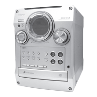
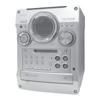
Details on identifying unit models and key system specifications.

System Operations, Clock, and Power Saving

Explains button functions, clock setting, and power saving modes.

Disassembly Procedures

External Panel and Internal Board Disassembly

Step-by-step guide for removing outer panels and internal circuit boards.

Internal Mechanisms and Motor Disassembly

Procedures for dismantling cassette, CD mechanisms, motors, and related assemblies.

Test Modes

Diagnostic Test Mode Procedures

Explains various test modes like CD Ship, GC, MC, and CD Service for diagnostics.

Mechanical Adjustments

Mechanical Torque Measurement Standards

Specifies required torque values for mechanical adjustments.

Electrical Adjustments

Tape Deck Electrical Adjustments

Procedures for head azimuth, bias, and tape speed adjustments.

CD Section Electrical Adjustments

Adjustments for CD playback including S-curve, RF level, and E-F balance.

Diagrams and Schematics

Circuit Board Layouts and System Block Diagrams

Visualizes circuit board placement and high-level system block diagrams.

Detailed Schematics and IC Information

Comprehensive schematics, PCB layouts, and IC pin descriptions.

Exploded Views

Unit Component Exploded Views

Visual breakdowns of unit components like panels, chassis, CD mechanism, and base unit.

Electrical Parts List

Component Breakdown by Section

Comprehensive lists of electrical parts (resistors, capacitors, ICs, etc.) by system section.

Related product manuals