EasyManua.ls Logo

Sony HCD-ZX80D Service Manual

Sony HCD-ZX80D
134 pages
To Next Page IconTo Next Page
Page #1 background imageLoading...
Page #1 background image
SERVICE MANUAL
DVD DECK RECEIVER
US Model
HCD-ZX80D
E Model
HCD-ZX80D/ZX100D
HCD-ZX80D/ZX100D
Ver. 1.2 2007.08
SPECIFICATIONS
9-887-251-03
2007H05-1
© 2007.08
Sony Corporation
Personal Audio Division
Published by Sony Techno Create Corporation
HCD-ZX80D is the amplifier, disc player, tape deck
and tuner section in FST-ZX80D/LBT-ZX80D.
HCD-ZX100D is the amplifier, disc player, tape deck
and tuner section in FST-ZX100D/LBT-ZX100D.
DVD
Model Name Using Similar Mechanism NEW
Section
DVD Mechanism Type CDM74HF-DVBU101
Optical Pick-up Block Name KHM-310CAB or KHM-313CAB
Tape deck Model Name Using Similar Mechanism NEW
Section Tape Transport Mechanism Type CWN42RR603
– Continued on next page –
Photo: HCD-ZX80D
This system incorporates Dolby* Digital, Dolby
Pro Logic (II) adaptive matrix surround decoder,
and the DTS** Digital Surround System.
* Manufactured under license from Dolby
Laboratories.
“Dolby”, “Pro Logic”, and the double-D
symbol are trademarks of Dolby
Laboratories.
**Manufactured under license from Digital
Theater Systems, Inc.
“DTS” and “ DTS Digital Surround” are
registered trademarks of Digital Theater
Systems, Inc.
Amplifier section
HCD-ZX100D
The following are measured at AC 120, 127, 220,
240V 50/60 Hz
DIN power output (rated): 130 W + 130 W
(6 ohms at 1 kHz, DIN)
Continuous RMS power output (reference)
Front speaker: 170 W + 170 W
(6 ohms at 1 kHz, 10% THD)
Center speaker: 80 W
(16 ohms at 1 kHz, 10%
THD)
Surround speaker: 170 W + 170 W
(6 ohms at 1 kHz, 10%
THD)
Subwoofer: 180 W (8 ohms at 100 Hz,
10% THD)
HCD-ZX80D
The following are measured at AC 120, 127, 220,
240V 50/60 Hz
DIN power output (rated):155 W + 155 W
(6 ohms at 1 kHz, DIN)
Continuous RMS power output (reference)
Front speaker: 200 W + 200 W
(6 ohms at 1 kHz, 10%
THD)
Center speaker: 80 W
(16 ohms at 1 kHz, 10%
THD)
Surround speaker: 200 W + 200 W
(6 ohms at 1 kHz, 10%
THD)
Inputs
VIDEO INPUT (phono jacks):
VIDEO: 1 Vp-p, 75 ohms
AUDIO L/R: Voltage
250 mV, impedance 47
kilohms
TV/SAT AUDIO IN L/R (phono jacks):
Voltage 250 mV/450 mV,
impedance 47 kilohms
MIC 1 or 2 (phone jack): Sensitivity 1 mV,
impedance 10 kilohms
Outputs
AUDIO OUT (phono jacks):
Voltage 250 mV,
impedance 1 kilohm
VIDEO OUT (phono jack):
Max. output level 1 Vp-p,
unbalanced, Sync.
negative load impedance
75 ohms
COMPONENT VIDEO OUT:
Y: 1 Vp-p, 75 ohms
P
B/CB: 0.7 Vp-p, 75 ohms
P
R/CR: 0.7 Vp-p, 75 ohms
AUDIO POWER SPECIFICATION
(HCD-ZX80D USA model only)
POWER OUTPUT AND TOTAL HARMONIC
DISTORTION:
With 6-ohm loads, both channels driven, from
120 Hz 10 kHz; rates 160 watts per channel
minimum RMS power, with no more than 10% total
harmonic distortion from 250 milliwatts to rated output.
Continuous RMS power output (reference)
Front speaker: 200 W + 200 W
(6 ohms at 1 kHz, 10% THD)
Center speaker: 80 W
(16 ohms at 1 kHz, 10%
THD)
Surround speaker: 200 W + 200 W
(6 ohms at 1 kHz, 10% THD)

Table of Contents

Question and Answer IconNeed help?

Do you have a question about the Sony HCD-ZX80D and is the answer not in the manual?

Sony HCD-ZX80D Specifications

General IconGeneral
TypeMini Hi-Fi Component System
ModelHCD-ZX80D
Cassette DeckDual cassette deck
OutputsHeadphone jack
Remote ControlYes

Summary

SPECIFICATIONS

AUDIO POWER SPECIFICATION

Details amplifier power output and total harmonic distortion.

SELF DIAGNOSIS FUNCTION

SAFETY CHECK-OUT

Perform safety checks after service, including AC leakage tests.

SECTION 1 SERVICING NOTES

NOTES ON HANDLING THE OPTICAL PICK-UP BLOCK OR BASE UNIT

Precautions for handling the optical pick-up block and base unit.

NOTES ON LASER DIODE EMISSION CHECK

Safety guidelines for checking laser diode emission.

UNLEADED SOLDER

Information on handling and characteristics of unleaded solder.

RELEASING THE DVD TRAY LOCK

Procedure to release the DVD tray lock for demonstration purposes.

SECTION 2 GENERAL

LOCATION OF CONTROLS

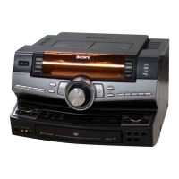
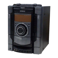
Identifies the location of controls on the unit and remote control.

SECTION 3 DISASSEMBLY

3-1. DISASSEMBLY FLOW

Outlines the sequence of disassembly steps for the set.

3-2. CASE

Details the procedure for removing the case of the unit.

3-3. ESCUTCHEON TOP BLOCK

Describes how to remove the escutcheon top block assembly.

3-4. LOADING PANEL

Explains the steps to remove the loading panel from the unit.

SECTION 4 TEST MODE

PANEL TEST MODE

Mode to test fluorescent indicator tube, LEDs, and knobs on the panel.

COMMON TEST MODE

Mode to check operations of amplifier and tape sections.

COLD RESET

Procedure to clear all data and reset the system to initial conditions.

TUNER STEP CHANGE

Toggles AM channel step interval between 9 kHz and 10 kHz.

SECTION 5 MECHANICAL ADJUSTMENTS

TORQUE MEASUREMENT

Details torque measurements for various mechanical parts.

SECTION 6 ELECTRICAL ADJUSTMENTS

RECORD/PLAYBACK HEAD AZIMUTH ADJUSTMENT

Adjustment procedure for the record/playback head azimuth on both decks.

RFMON LEVEL CHECK

Checks the RFMON signal level using an oscilloscope.

SECTION 7 DIAGRAMS

7-1. BLOCK DIAGRAM – RF SERVO/VIDEO SECTION –

Provides the block diagram for the RF servo and video sections.

7-4. BLOCK DIAGRAM – AUDIO SECTION –

Displays the block diagram for the audio section.

7-7. PRINTED WIRING BOARD – DMB15 Board (Side A) –

Displays the PWB layout for the DMB15 board (Side A).

7-15. PRINTED WIRING BOARD – VIDEO Board –

Displays the PWB layout for the video board.

SECTION 8 EXPLODED VIEWS

8-1. CASE, ESCUTCHEON TOP SECTION

Exploded view showing the case and escutcheon top components.

8-3. TAPE MECHA DECK SECTION

Exploded view of the tape mechanism deck section and its parts.

8-8. DVD MECHANISM DECK SECTION-1 (CDM74HF-DVBU101)

Exploded view of the DVD mechanism deck (part 1).

SECTION 9 ELECTRICAL PARTS LIST

DMB15 BOARD PARTS

Lists electrical parts for the DMB15 board.

MAIN BOARD PARTS

Lists electrical parts for the main board.

EFFECTOR BOARD PARTS

Lists electrical parts for the effector board.

PANEL BOARD PARTS

Lists electrical parts for the panel board.

Related product manuals