Do you have a question about the Sony HCR-S7AV and is the answer not in the manual?
Specifies voltage and frequency for different regions.
Details power usage in watts for normal and standby modes.
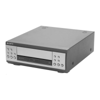
Describes the basic system components and laser type.
Provides precautions for handling the optical pick-up to prevent damage.
Instructions for safely checking laser diode emission.
Identifies model variants based on rear panel labels.
Lists components with page references for details.
Identifies buttons on the remote control.
Outlines the sequence for disassembling the unit.
Explains how to remove the front panel section.
Mode used for testing CD player functions.
Allows optional control of the CD sled motor for maintenance.
Procedure to check the symmetry and peak level of the S-curve waveform.
Explains notations used in diagrams and boards.
Details the procedure for testing CD-TEXT display functionality.
Identifies parts of the main unit.
Explains how to remove the CD mechanism deck.
Displays microcomputer/mechanism deck version information.
Procedure to check the clarity and level of the RF signal waveform.
Checks and adjusts waveform center voltage against DVC.
Illustrates the physical placement of various circuit boards within the unit.
Lists all electrical components for the BD board.
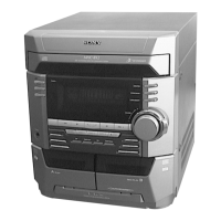
Describes the speaker configuration (e.g., 3-way, 2-unit).
Details the procedure for removing the speaker's front panel.
Exploded view and parts list for the SS-CT270 speaker.
Details specifications for the amplifier section.
Covers power requirements, consumption, dimensions, and mass.
Describes the procedure for accessing the front amp board.
Outlines the sequence for disassembling the unit.
Resets the system to clear all stored data.
Explains notations used in diagrams and boards.
Exploded view of the main chassis and its components.
Details specifications for the tuner section.
Identifies model variants based on rear panel labels.
Identifies controls on the front and rear panels.
Outlines the sequence for disassembling the unit.
Explains how to remove the FM/AM tuner pack.
Mode used for testing various functions.
Explains notations used in diagrams and boards.
Exploded view of the main chassis and its components.
Details the recording system type and frequency response.
Identifies model variants based on rear panel labels.
Identifies controls on the front and rear panels.
Outlines the sequence for disassembling the unit.
Explains how to remove the tape mechanism deck.
Mode for testing specific deck operations.
Lists torque specifications for various adjustments.
Procedure to adjust the azimuth of the record/playback heads.
Explains notations used in diagrams and boards.
Presents block diagram for the main board IC.
Exploded view of the general chassis and front panel assembly.
| Brand | Sony |
|---|---|
| Model | HCR-S7AV |
| Category | Stereo System |
| Language | English |