HCD-FLX9W
3535
HCD-FLX9W
set
DSP board
VIDEO/SAT jack (J701)
315 Hz, 50 mV (
−
23.8 dB)
blank tape
CS-123
600
Ω
attenuator
AF OSC
+
–
set
recorded
portion
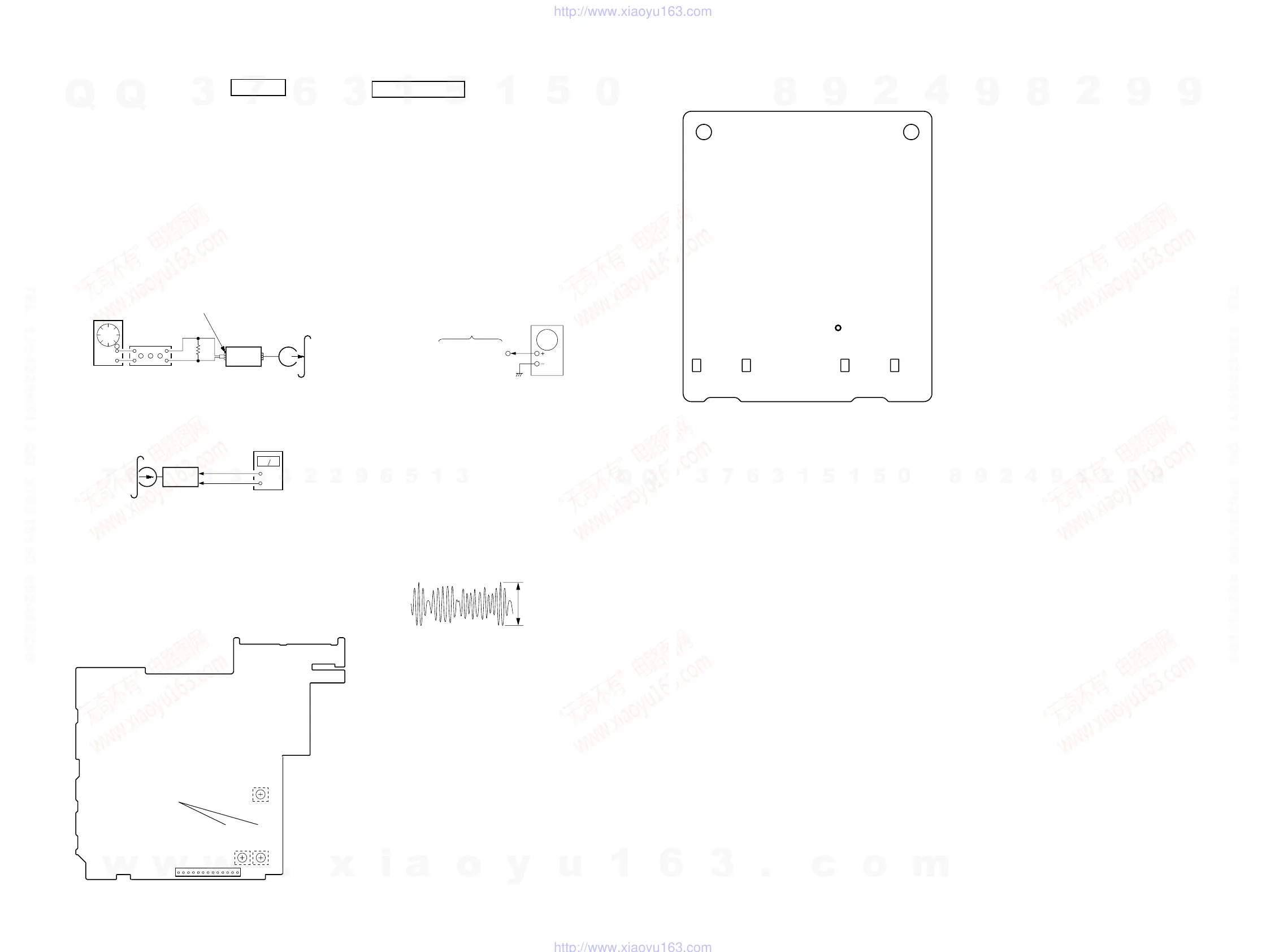
SP RELAY board
CN804 Pin
3
(GND)
SP RELAY board
CN804
Pin
5
(R-CH)
level meter
CN804
13
1
− SP RELAY BOARD (Conductor Side) −
REC BIAS
ADJUSTMENT
REC LEVEL
ADJUSTMENT
(L-CH)
(R-CH)
RV52
RV2
RV53
REC LEVEL ADJUSTMENT DECK B
Procedure:
In the MC test mode, the “REC memory mode” is convenient for
this adjustment. In the “REC memory mode” , when the REC starts
the input signal FUNCTION is switched to VIDEO automatically.
When the REC stops, the tape returns near to the recording start
position.
1. Press [VIDEO/SAT] button to select VIDEO. (This step is not
necessary if the above test mode has already been set)
2. Insert a tape into deck B.
3. After press [REC PAUSE/START] button, press [REC PAUSE/
START] button, then recording start.
4. Mode: Record
5. Mode: Playback
6. Confirm the play back signal recorded in step 3 becomes
adjustable level as follows.
If these levels are not adjustable level, adjust the RV53 (R-
CH) on the SP RELAY board to repeat steps 4 and 5.
Adjustable level:
CN804 PB level: 47.2 to 53.0 mV (−24.3 to −23.3 dB)
Adjustment Location: SP RELAY board
DVD SECTION
About the dicision to pass or fail of the optical pick-up block, refer
to “DICISION TO PASS OR FAIL OF THE OPTICAL PICK-UP
BLOCK” (see page 8)
AUTO SERVO ADJUSTMENT
After parts related to the servo circuit (RF amplifier (IC001), DSP
(IC509), motor driver (IC501), EEPROM (IC903) so on) are
replaced, re-adjusting the servo circuit is necessary. Select “ALL”
at “1. DRIVE AUTO ADJUSTMENT” (Refer to page 27 in TEST
MODE) and adjust DVD-SL (single layer), CD and DVD-DL (dual
layer).
DIAT SIGNAL RF LEVEL ADJUSTMENT
This adjustment is performed in order to adjust the transmission
distance of RF signal for DIAT communication.
Connection:
Procedure:
1. Connect the oscilloscope to JL7003 (RF AMP OUT) and GND
on the TX board.
2. Connect DIR-T1 to DIR-T1 jack (J7001).
Note: Be sure to connect DIR-T1 before the adjust.
3. Adjust RV7001 on the TX board so that the center of waveform
becomes 1.0 Vp-p.
4. Confirm trigger is locked.
5. Adjust RV7001 on the TX board so that the center of waveform
becomes 2.2 to 2.4 Vp-p.
RF Signal Reference Waveform
VOLT/DIV : 500mV
TIME/DIV : 500ns
level : 2.2 to 2.4 Vp-
JL7003
(RF AMP OUT)
TX board
oscilloscope
– TX Board (Component Side) –
JL7003
(RF AMP OUT)
Adjustment Location:
w
w
w
.
x
i
a
o
y
u
1
6
3
.
c
o
m
Q
Q
3
7
6
3
1
5
1
5
0
9
9
2
8
9
4
2
9
8
T
E
L
1
3
9
4
2
2
9
6
5
1
3
9
9
2
8
9
4
2
9
8
0
5
1
5
1
3
6
7
3
Q
Q
TEL 13942296513 QQ 376315150 892498299
TEL 13942296513 QQ 376315150 892498299
http://www.xiaoyu163.com
http://www.xiaoyu163.com