EasyManua.ls Logo

Sony HD-IS10 User Manual

Sony HD-IS10
82 pages
To Next Page IconTo Next Page
Page #1 background imageLoading...
Page #1 background image
SERVICE MANUAL
DVD system
Laser
(DVD: λ = 645 - 660 nm) (CD: λ = 770 - 800 nm)
Emission duration: continuous
Signal format system US, Canadian and Latin American models: NTSC
European model: PAL/NTSC
Other models: NTSC/PAL
Semiconductor laser
Video section
Outputs VIDEO: 1 Vp-p 75 ohms
COMPONENT: Y: 1 Vp-p 75ohms
PB/CB, PR/CR: 0.7Vp-p 75 ohms
HDMI OUT: Type A (19 pin)
Control unit
Dimensions (approx.) 215 × 105 × 207 mm (8
1
/
2
× 4
1
/
4
× 8
1
/
4
inches)
(w/h/d)
Mass (approx.) 3.0 kg (6 lb 10 oz)
Power output
Except Latin American model:
(DIGITAL MEDIA PORT) DC OUT: 5 V, 700 mA
Design and specifications are subject to change without notice.
Tuner section
System PLL quartz-locked digital synthesizer
FM tuner section
Tuning range US and Canadian models:
87.5 108.0 MHz (100kHz step)
Other models: 87.5 108.0 MHz (50kHz step)
Antenna (aerial) FM wire antenna (aerial)
Antenna (aerial) terminals 75 ohms, unbalanced
Intermediate frequency 10.7 MHz
AM tuner section
Tuning range US, Canadian, Australian and Latin American models:
531 1,710kHz (with the interval set at 9kHz)
530 1,710kHz (with the interval set at 10kHz)
Other models:
531 1,602kHz (with the interval set at 9kHz)
530 1,610kHz (with the interval set at 10kHz)
European and Saudi Arabian models:
531 1,602kHz (with the interval set at 9kHz)
Antenna (aerial)
AM loop antenna (aerial)
Intermediate frequency
450 kHz
DVD RECEIVER
US Model
Canadian Model
AEP Model
UK Model
E Model
Australian Model
Chinese Model
HCD-IS10
SPECIFICATIONS
9-887-730-02
2007J05-1
© 2007.10
Sony Corporation
Home Audio Division
Published by Sony Techno Create Corporation
HCD-IS10 is the DVD system, tuner
and video section in DAV-IS10.
In this set, repair in the sate of having
connected with SA-WSIS10.
Model Name Using Similar Mechanism NEW
DVD Mechanism Type CDM86A-DVBU101
Optical Pick-up Block Name KHM-313CAB
Ver. 1.1 2007.10
This product incorporates copyright protection technology that is protected by
U.S. patents and other intellectual property rights. Use of this copyright
protection technology must be authorized by Macrovision, and is intended for
home and other limited viewing uses only unless otherwise authorized by
Macrovision. Reverse engineering or disassembly is prohibited.
This system incorporates with Dolby* Digital and Dolby Pro Logic (II)
adaptive matrix surround decoder and the DTS** Digital Surround System.
* Manufactured under license from Dolby Laboratories.
“Dolby,” “Pro Logic,” and the double-D symbol are trademarks of Dolby Laboratories.
**Manufactured under license from DTS, Inc.
“DTS” and “DTS Digital Surround” are registered trademarks of DTS, Inc.
w
w
w
.
x
i
a
o
y
u
1
6
3
.
c
o
m
Q
Q
3
7
6
3
1
5
1
5
0
9
9
2
8
9
4
2
9
8
T
E
L
1
3
9
4
2
2
9
6
5
1
3
9
9
2
8
9
4
2
9
8
0
5
1
5
1
3
6
7
3
Q
Q
TEL 13942296513 QQ 376315150 892498299
http://www.xiaoyu163.com

Table of Contents

Question and Answer IconNeed help?

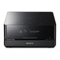
Do you have a question about the Sony HD-IS10 and is the answer not in the manual?

Sony HD-IS10 Specifications

General IconGeneral
BrandSony
ModelHD-IS10
CategoryReceiver
LanguageEnglish

Summary

Service Manual Overview

Specifications

Technical details of the DVD system, tuner, video section, and controls.

Service Precautions

Self Diagnosis Function

Explanation of the self-diagnosis function and error code interpretation for troubleshooting.

Safety-Related Component Warnings

Warning about critical safety components identified by marks for safe operation.

Service Procedures

Optical Pick-up Block Removal Precautions

Important precautions and bridging instructions for safely removing the optical pick-up block.

Disassembly Procedures

Disassembly Flow Chart

Step-by-step diagram showing the order of disassembly for various parts.

DVD Service Mode

Executing IOP Measurement

Detailed procedure for executing IOP measurement, crucial after base unit replacement.

Electrical Adjustments

Executing IOP Measurement Reference

Instructions to perform IOP measurement, referencing page 25 for details.

Diagrams

Block Diagram - DVD Servo, Video Section

Block diagram illustrating the DVD servo and video signal paths and components.

Block Diagram - Main, HDMI Section

Block diagram showing the main processing unit and HDMI interface connections.

Block Diagram - Panel, Power Supply Section

Block diagram illustrating the front panel interface and power supply distribution.

Schematic Diagram - DVD Section (1/5)

Detailed schematic of the DVD section, part 1 of 5, focusing on IC111 and other components.

Schematic Diagram - DVD Section (2/5)

Detailed schematic of the DVD section, part 2 of 5, showing IC105, IC102, IC110, IC107, IC104, IC103.

Schematic Diagram - DVD Section (3/5)

Detailed schematic of the DVD section, part 3 of 5, focusing on IC3801 and related components.

Schematic Diagram - DVD Section (4/5)

Detailed schematic of the DVD section, part 4 of 5, showing IC201 and its connections.

Schematic Diagram - DVD Section (5/5)

Detailed schematic of the DVD section, part 5 of 5, showing HDMI transmitter and other ICs.

Printed Wiring Boards - DVD Section (1/2) - Side A

Component layout for the DVD section (Side A), showing locations of ICs and other parts.

Printed Wiring Boards - DVD Section (1/2) - Side B

Component layout for the DVD section (Side B), showing component placement.

Printed Wiring Board - Main Board (Component Side)

Component layout for the main board (component side), showing ICs and connectors.

Printed Wiring Board - Main Board (Conductor Side)

Component layout for the main board (conductor side), showing traces and connections.

Schematic Diagram - Main Board (1/2)

Detailed schematic of the main board, part 1 of 2, showing IC201 and related circuits.

Schematic Diagram - Main Board (2/2)

Detailed schematic of the main board, part 2 of 2, showing IC272, IC273 and connections.

IC Pin Function Descriptions

IC101 CXD9889R Pinout Details

Detailed description of each pin function for IC101 (CXD9889R) on the DMB-IVHD board.

IC101 CXD9889R Pinout (Continued)

Continuation of pinout details for IC101 (CXD9889R), covering pins 243-256.

IC701 CXD9873Q Pinout Details

Detailed description of each pin function for IC701 (CXD9873Q) on the DMB-IVHD board.

IC701 CXD9873Q Pinout (Continued)

Continuation of pinout details for IC701 (CXD9873Q), covering pins 65-80.

IC101 M30620MCP-A18FPU0 Pinout Details

Detailed description of each pin function for IC101 (M30620MCP-A18FPU0) on the MAIN board.

IC101 M30620MCP-A18FPU0 Pinout (Continued)

Continuation of pinout details for IC101 (M30620MCP-A18FPU0), covering pins 49-100.

Electrical Parts List

Related product manuals