90
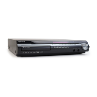
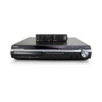
HCD-X1
SECTION 7
EXPLODED VIEWS
Ref. No. Part No. Description Remark
Ref. No. Part No. Description Remark
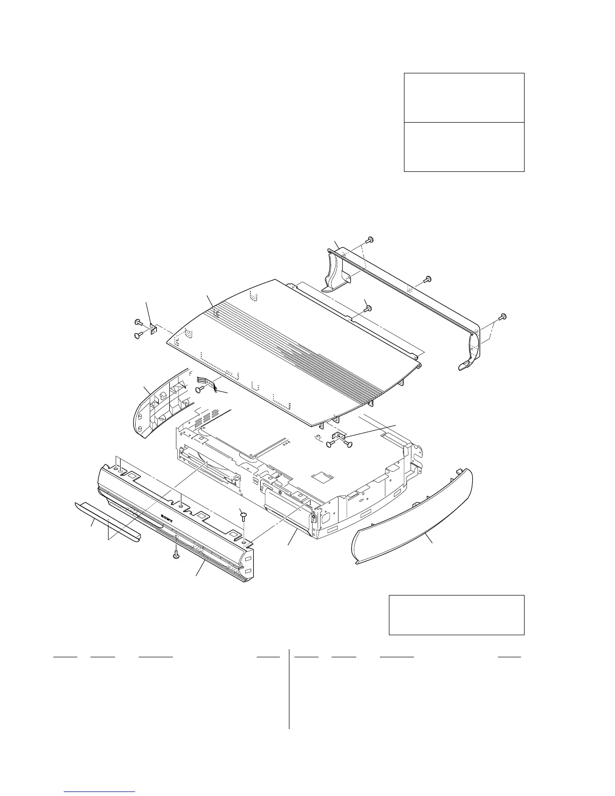
1 X-2055-333-2 PANEL, LOADING ASSY
3 2-436-530-01 SCREW +P TP 3X8 BT
4 2-588-803-01 PANEL (L), SIDE
5 3-704-515-22 SCREW (BV/RING)
6 2-588-805-01 COVER (REAR)
7 2-588-833-01 CASE (AL) (US, CND, RU)
7 2-588-833-11 CASE (AL) (AEP, UK)
7 2-588-833-21 CASE (AL) (SP)
8 2-588-804-01 PANEL (R), SIDE
9 2-588-844-01 PLATE (ALMI), GROUND
#1 7-685-646-79 SCREW +BVTP 3X8 TYPE2 IT-3
7-1. CASE (AL), SIDE PANEL SECTION
• Items marked “*” are not stocked since they
are seldom required for routine service. Some
delay should be anticipated when ordering
these items.
• The mechanical parts with no reference
number in the exploded views are not supplied.
• Accessories are given in the last of the
electrical parts list.
NOTE:
• -XX and -X mean standardized parts, so they
may have some difference from the original
one.
• Color Indication of Appearance Parts
Example:
KNOB, BALANCE (WHITE) . . . (RED)
↑↑
Parts Color Cabinet's Color
• Abbreviation
CND : Canadian model
RU : Russian model
SP : Singapore model
1
#1
#1
#1
#1
#1
#1
#1
#1
#1
not supplied
not supplied
front panel section
MAIN board,
POWER-AMP board
and chassis section
3
4
5
6
7
9
8
Les composants identifiés par une
marque 0 sont critiquens pour la
sécurité.
Ne les remplacer que par une pièce
portant le numéro spécifié.
The components identified by mark
0 or dotted line with mark 0 are
critical for safety.
Replace only with part number
specified.
Ver. 1.1
Note: When remove the loading assy panel
(Ref. No. 1), make sure to refor to
the DISASSEMBLY “3-5. FRONT
PANEL SECTION” (page 14).