12
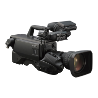
Locations and Functions of Parts
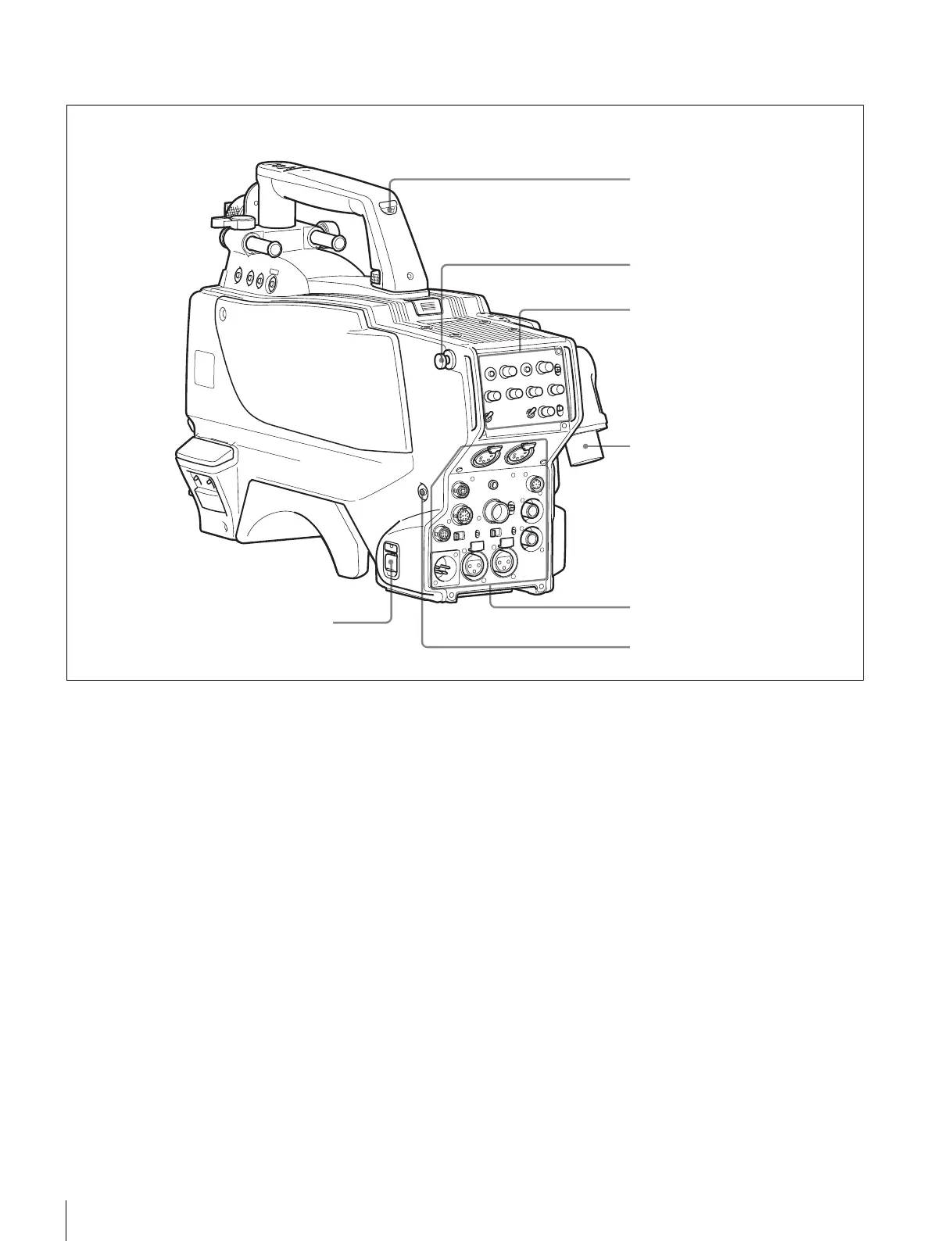
Rear
a CAMERA POWER switch
CCU: Power supply will be received from the camera
control unit.
EXT: Power supply will be received through the DC IN
connector.
b Tally lamp and switch
ON: The tally lamp lights upon a tally signal input to the
connected camera control unit or a call signal generated
by pressing a CALL button.
OFF: The tally lamp is prevented from lighting.
c CCU (Camera Control Unit) connector (optical/
electrical multi-connector)
Connect a camera control unit using an optical electro-
composite cable.
d CALL button
When you press this button, the red tally lamp of the RCP-
700/900-series Remote Control Panel or the MSU-900/950
Master Setup Unit, will light. Use to call the operator of the
RCP or MSU.
a CAMERA POWER switch
Shoulder strap fitting post (page 8)
c CCU connector
d CALL button
Operation panel (page 13)
Connector panel (page 14)
b Tally lamp and switch