Do you have a question about the Sony HTC-NX1 and is the answer not in the manual?
Details about the CD playback system, laser type, and output characteristics.
Specifications for the tape deck, including recording system and frequency response.
Information on CLASS 1 LASER product classification and safe handling of the optical pick-up.
Guidelines for handling chip components, flexible circuit boards, and general repair cautions.
Procedure for powering the unit during service, especially when external power is required.
Step-by-step guide for cleaning the optical pick-up lens with specific instructions.
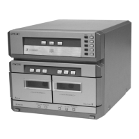
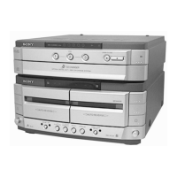
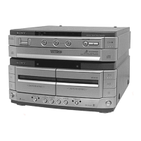
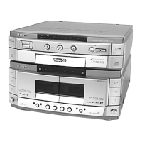
Identification and description of the front panel controls and indicators on the unit.
Procedures for removing the main case and the front panel assembly from the unit.
Steps for removing the CD mechanism deck and the tape mechanism deck sections.
Procedures for removing the CD base unit and the main circuit board.
Steps for disassembling the fitting base, bracket, magnet assembly, and tray.
Instructions for assembling the chassis, stocker, slider, and gear mechanisms.
Details on installing the slider (selection) and stocker sections of the mechanism.
Instructions for installing the chassis (mold B) section, including gear and slider placement.
Procedure to activate a mode where all LEDs light up for key function testing.
Mode to move the optical pick-up to a vibration-durable position for customer return.
Test mode for the tape deck, with variations based on connection to STR-NX1/NX3 or power feed jig.
Specifications and procedures for measuring torque on various mechanical parts during adjustments.
Settings and procedures for tape deck electrical adjustments, including test tape usage.
Procedures for adjusting tape speed and playback level for both decks.
Procedures for adjusting recording bias and recording level for the tape deck.
Procedures for checking the S-curve and RF signal level using an oscilloscope.
General notes and conventions used for interpreting wiring boards and schematic diagrams.
Diagram showing the physical location of various circuit boards within the unit.
Printed wiring layout for the BD board, showing component placement on both sides.
Schematic circuit diagram for the BD board, detailing connections and components.
Printed wiring layouts for CD motor and sensor related boards.
Schematic circuit diagram for CD motor and sensor related boards.
Printed wiring layout for the main audio board, showing component placement.
Schematic circuit diagram for the main audio board, detailing signal paths and components.
Printed wiring layout for the LEAF SW board.
Schematic circuit diagram for the LEAF SW board.
Printed wiring layout for the main board, showing component positions.
Part one of the schematic diagram for the main board, showing circuit connections.
Part two of the schematic diagram for the main board, continuing circuit connections.
Printed wiring layouts for the panel boards (TC-A, TC-B).
Detailed pinout and function description for IC101 on the main board.
Exploded diagram of the unit's case and chassis, with part numbers.
Exploded diagram of the front panel section, showing assembly details.
Exploded diagram of the CD mechanism deck section (part 1).
Exploded diagram of the CD mechanism deck section (part 2).
Exploded diagram of the CD base unit, showing its components and assembly.
Exploded diagram of the tape mechanism deck section (part 1).
Exploded diagram of the tape mechanism deck section (part 2).
Lists of capacitors, coils, transistors, resistors, and connectors for the audio section.
Components including variable resistors, transformers, ICs, and ferrite beads.
Lists of diodes, ICs, switches, and photo interrupters used in various boards.
Lists of capacitors and resistors for LEAF SW, LOAD MOTOR, and MAIN boards.
Lists of connectors, diodes, coils, and transistors from the MAIN board.
Lists of resistors, variable resistors, and vibrators for MAIN, OUT SW, and PANEL boards.
Lists of LEDs, transistors, and switches found on PANEL boards.
Final lists of resistors, switches, LEDs, miscellaneous parts, and hardware.
| Brand | Sony |
|---|---|
| Model | HTC-NX1 |
| Category | Stereo System |
| CD Player | Yes |
| Cassette Deck | Yes |
| Bluetooth | No |
| Remote Control | Yes |
| Speakers | 2 |
| Type | Mini System |
| Supported Media | CD |
| Tuner | FM, AM |
| Weight | 4.5 kg |