EasyManua.ls Logo

Sony HTC-V5550 User Manual

Sony HTC-V5550
64 pages
To Next Page IconTo Next Page
Page #1 background imageLoading...
Page #1 background image
HTC-V5550
E Model
Chinese Model
SERVICE MANUAL
COMPACT DISC DECK
MICROFILM
This stereo system is equipped with the Dolby B-
type noise reduction system.
* Manufactured under license from Dolby
Laboratories Licensing Corporation.
DOLBY, the double-D symbol a and “PRO LOGIC”
are trademarks of Dolby Laboratories Licensing
Corporation.
Model Name Using Similar Mechanism HCD-V717
CD CD Mechanism Type CDM38-5BD24
Section Base Unit Type BU-5BD24
Optical Pick-up Name KSS-213BA/F-NP
Tape deck
Model Name Using Similar Mechanism HTC-W555
Section Tape Transport Mechanism Type
TCM-230AWR2
TCM-230PWR2
This set is the deck and Video CD
section in MHC-V5550/V7770.
SPECIFICATIONS
Video section
Inputs AV INPUT VIDEO (phono jack):
1Vp-p, 75
VIDEO IN (phono jack)
1Vp-p, 75
Outputs MONITOR OUT (phono jack):
1Vp-p, 75
VIDEO OUT (phono jack)
1Vp-p, 75
S-VIDEO (4-pin/mini-DIN jack):
Y: 1Vp-p, unbalanced, sync negative
C: 0.286Vp-p, load impedance 75
VIDEO CD/CD player section
System Compact disc, digital audio video system
Laser Semiconductor laser (λ=780nm)
Emission duradon: continuous
Laser output Max. 44.6µW*
*This output is the value measured at a
diatance of 200 mm from the objective
lens surface on the Optical Pick-up Block
with 7 mm aperture.
Frequency response 20 Hz – 20 kHz (±1 dB)
Wavelength 780 – 790 nm
Signal to noise ratio More than 90 dB
Dynamic range More than 90 dB
Video Color System format
NTSC, PAL
CD OPTICAL DIGITAL OUT
(Square optical connector jack, rear panel)
Wavelength 600 nm
Output Level –18 dBm
Tape player section
Recording system 4-track 2-channel stereo
Frequency response 40 – 13,000 Hz (±3 dB),
(DOLBY NR OFF) using Sony TYPE
cassette
40 – 14,000 Hz (±3 dB),
using Sony TYPE
cassette
Design and specifications are subject to change without notice.
w
w
w
.
x
i
a
o
y
u
1
6
3
.
c
o
m
Q
Q
3
7
6
3
1
5
1
5
0
9
9
2
8
9
4
2
9
8
T
E
L
1
3
9
4
2
2
9
6
5
1
3
9
9
2
8
9
4
2
9
8
0
5
1
5
1
3
6
7
3
Q
Q
TEL 13942296513 QQ 376315150 892498299
http://www.xiaoyu163.com
Question and Answer IconNeed help?

Do you have a question about the Sony HTC-V5550 and is the answer not in the manual?

Sony HTC-V5550 Specifications

General IconGeneral
BrandSony
ModelHTC-V5550
CategoryStereo System
CD PlayerYes
BluetoothNo
TypeMini System
Tuner BandsFM/AM
USB PortNo

Summary

Servicing Note

Opening Disc Tray and Rotary Encoder Installation

Procedures for opening the disc tray and installing the rotary encoder.

Unit Operation by Itself

Instructions for operating the unit independently using a jig or power supply.

Special Operating Modes

Details on Cold Reset, CD Delivery, LED All Lit, Key Check, and Aging modes.

General

Location of Parts and Controls

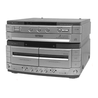
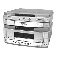
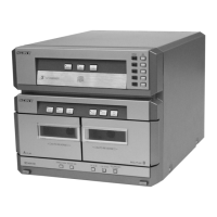
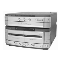
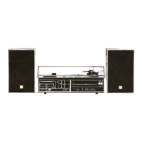
Identifies and describes the location of all parts and controls on the unit.

Disassembly

Loading Panel and Back Panel Disassembly

Steps for disassembling the loading panel and back panel/CD mechanism deck.

Front Panel and TC Mechanism Disassembly

Steps for disassembling the front panel and TC mechanism deck/cassette holder.

Disc Tray Disassembly

Procedure for disassembling the disc tray.

Mechanical Adjustments

Precautions and Torque Measurement

Important precautions and torque measurement procedures for mechanical adjustments.

Electrical Adjustments

Preparation and Azimuth Adjustment

Notes before adjustment and azimuth adjustment procedure for heads.

Tape Speed and Playback Level Adjustments

Procedures for adjusting tape speed and playback signal levels for decks.

Record Bias and Level Adjustments

Procedures for adjusting record bias and signal levels for the tape deck.

CD Section

Notes and Checks

Important notes and procedures for checking S-curve and RF level.

Video Section

Frequency Adjustment

Steps to adjust the video signal frequency.

Diagrams

Circuit Boards Location

Shows the physical location of all circuit boards within the unit.

Block Diagrams

Block diagrams illustrating Servo, Audio/Video CD, and Tape Deck sections.

Printed Wiring Boards

Layouts for CD, Tape Deck, Main, Panel, Leaf SW, and Video sections.

Schematic Diagrams

Schematic diagrams for Deck, Main, Panel, CD Motor, and Video sections.

Waveforms

Displays oscilloscope waveforms for BD board, Video board, and ICs.

IC Block Diagrams and Pin Functions

Block diagrams and detailed pin functions for key ICs like CXD2545Q and others.

Power Section

Power Supply Circuit Details

Details the power supply circuits and their components.

Exploded Views

Case and Back Panel Exploded View

Exploded view showing parts of the case and back panel assembly.

Front Panel Exploded View

Exploded view showing parts of the front panel assembly.

CD Mechanism Exploded Views

Exploded views of the CD mechanism sections 1 and 2.

Base Unit Exploded View

Exploded view showing parts of the base unit assembly.

TC Mechanism Exploded Views

Exploded views of the TC mechanism sections 1 and 2.

Electrical Parts List

Audio Board Parts List

List of electrical components for the Audio board.

Audio Board Parts List (Continued)

Continuation of the electrical components list for the Audio board.

BD CD (P), Connector, Leaf SW Parts List

List of components for BD CD (P) connector and Leaf SW.

Leaf SW and Main Board Parts List

List of components for Leaf SW and Main board.

Main Board Motor (Slide) Parts List

List of components for the Main board motor (slide).

Motor (Turn), Regulator, Sensor, TC Boards Parts List

List of components for Motor (Turn), Regulator, Sensor, and TC boards.

TC (P) and Video Parts List

List of components for the TC (P) and Video boards.

Video and Video In/Out Parts List

List of components for Video and Video In/Out sections.

Video Parts List (Continued)

Continuation of the component list for the Video section.

Hardware List

Hardware List Details

List of screws and other hardware used in the assembly.

Related product manuals