HXR-NX5C/NX5E/NX5J/NX5M/NX5N/NX5P/NX5U
1-1
1. SERVICE NOTE
1-1. POWER SUPPLY DURING REPAIRS
In this unit, about 10 seconds after power is supplied to the battery terminal using the regulated power supply (8.4V), the power is shut off
so that the unit cannot operate.
These following method is available to prevent this.
Method:
Use the AC adaptor/charger (AC-VQ1050 etc.) and connecting cord (DK-415).
1-2. PRECAUTION ON REPLACING THE VC-582 BOARD
DESTINATION DATA
When you replace to the repairing board, the written destination data of repairing board also might be changed to original setting.
Start the Adjust Manual in the Adjust Station and execute the “Destination data write”.
USB SERIAL SAVE
When you replace to the repairing board, get the data from the former one.
Start the Adjust Manual in the Adjust Station and perform “USB SERIAL SAVE” to get the data.
USB SERIAL No.
The set is shipped with a unique ID (USB Serial No.) written in it.
This ID has not been written in a new board for service, and therefore it must be entered after the board replacement.
Start the Adjust Manual in the Adjust Station and execute the “USB serial No. input”.
– ENGLISH –
1-3. SELF-DIAGNOSIS FUNCTION
1-3-1. Self-diagnosis Function
When problems occur while the unit is operating, the self-diagnosis
function starts working, and displays on the Viewfinder or the LCD
screen what to do. This function consists of two display; selfdiag-
nosis display and service mode display.
Details of the self-diagnosis functions are provided in the Instruc-
tion manual.
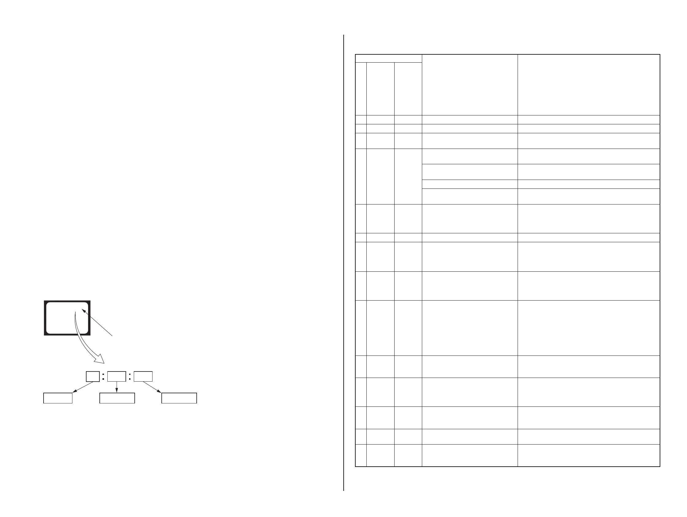
1-3-2. Self-diagnosis Display
When problems occur while the unit is operating, the counter of the
Viewfinder or the LCD screen shows a 4-digit display consisting of
an alphabet and numbers, which blinks at 3.2 Hz. This 5-character
display indicates the “repaired by:”, “block” in which the problem
occurred, and “detailed code” of the problem.
1 1
3 1C
Repaired by:
Refer to “1-3-3. Self-diagnosis Code Table”.
Indicates the appropriate
step to be taken.
E.g.
31 ....Reload the tape.
32 ....Turn on power again.
Block
Detailed Code
Blinks at 3.2Hz
C : Corrected by customer
H : Corrected by dealer
E : Corrected by service
engineer
Viewfinder or LCD screen
C : 3 1 : 1 1
1-3-3. Self-diagnosis Code Table
Self-diagnosis Code
Symptom/State Correction
Repaired by:
Block
Function
Detailed
Code
C 0 4 0 0 Non-standard battery is used. Use the InfoLITHIUM battery.
C 0 6 0 0 The battery pack temperature is high. Change the battery pack or place it in a cool place.
C1 3 0 1
“memory card” is unformatted.
“memory card” is broken.
Format the “memory card”.
Insert a new “memory card”
C1 3 0 4
The external storage media has connected
loose.
Insert again the external storage media precisely.
Abnormality occurs in the external stor-
age media.
Format again the external storage media.
The external storage media is broken. Replace it with new one.
Abnormality occurs in between the main
and the external storage media.
Turn power off and turn power on again.
C3 2 6 0
Difficult to adjust focus
(Cannot initialize focus)
Retry turn the power on by the power switch. If it does not
recover, check the focus MR sensor of lens block (pin 0, qs
of CN6602 on the VC-582 board). If it is OK, check the focus
motor drive IC (IC6002 on the VC-582 board).
E 2 0 0 0 Flash memory data are rewritten. Make flash memory data correct value. (Note 1)
E6 1 1 0
Zoom operations fault
(Cannot initialize zoom lens.)
Inspect the lens block zoom MR sensor (pin es, ef of CN6602
on the VC-582 board) when zooming is performed when the
zoom lever is operated, or the zoom motor drive circuit (IC6002
on the VC-582 board) when zooming is not performed.
E6 1 1 1
The abnormalities in initialization of
the focus lens and the abnormalities in
initialization of the zoom lens occurred
simultaneously.
Check both C: 32: 60 and E: 61: 10 of the self-diagnosis
code.
E6 1 3 0
Reset position detect error when stepper
iris is initialized.
Turn on the power and set to T (telephoto) end by rotating the
ZOOM manual ring. While observing the iris blades in the
lens, turn on the power again and check the iris blades in the
lens work properly. Inspect the iris drive motor of lens drive
block (Pin qh to ql of CN6602 on the VC-582 board), when
the iris does not operate. Inspect the iris reset sensor of lens
drive block (Pin qd to qg of CN6602 on the VC-582 board),
when the iris operate.
E6 2 0 0
Steadyshot function does not work well.
(With pitch angular velocity sensor out-
put stopped.)
Inspect pitch angular velocity sensor (SE8501 on the GY-022
board) peripheral circuits.
E6 2 0 1
Steadyshot function does not work
well.
(With yaw angular velocity sensor output
stopped.)
Inspect yaw angular velocity sensor (SE8502 on the GY-022
board) peripheral circuits.
E 6 2 0 2 Abnormality of IC for steadyshot.
Inspect the steadyshot circuit (IC6401 on the VC-582 board).
If it does not recover, replace the VC-582 board. (Note 2) If
an error occurs again, replace the lens block.
E6 2 0 3
IC for steadyshot and micro controller
communication abnormality among.
Inspect the steadyshot circuit (IC6401 on the VC-582 board).
E 6 2 1 0 Shift lens initializing failure
Inspect the EEPROM (IC5602, IC5603 on the VC-582 board).
If it does not recover, replace the VC-582 board. (Note 2) If an
error occurs again, replace the lens block.
Note 1: Start the Adjust Manual in the Adjust Station and refer to the “Destination data write”.
Note 2: When replacing the VC-582 board, remove the EEPROM (IC5602, IC5603) from the VC-582 board that is going to be repaired. Install the removed
EEPROM (IC5602, IC5603) to the replaced VC-582 board.
 Loading...