– 3 –
– 4 –
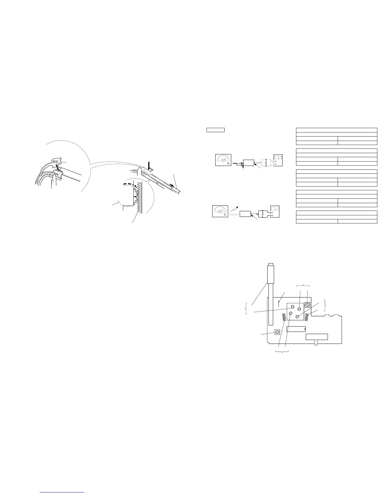
Note: Follow the assembly procedure in the numerical order given.
SECTION 3
DIAL POINTER SETTING
1
Slide the pointer
to the inner part.
2
Turn the VC gear
fully in the arrow
B
direction.
3
Insert the pointer to the gear
fitting the concave position
of the pointer to the convex
position of the
ear.
pointer
A
Note: When take off the pointer,
remove to direction of the arrow
A
.
B
SECTION 4
ELECTRICAL ADJUSTMENTS
[AM Section]
Setting:
Band select switch: AM
0dB=1 µV
[FM Section]
Setting:
Band select switch: FM
Repeat the procedures in each adjustment several times, and the
frequency coverage and tracking adjustments should be finally done
by the trimmer capacitors.
FM RF SSG
±
22.5 kHz frequency
deviation by 400 Hz
signal
Output level: as low as possible
+
–
level meter
earphone jack
set
FM antenna terminal
8
Ω
AM RF SSG
30% amplitude
modulation by
400 Hz signal
Output level: as low as possible
Put the lead-wire
antenna close to
the set.
+
–
level mete
earphone jack
set
8
Ω
FM FREQUENCY COVERAGE ADJUSTMENT
Adjust for a maximum reading on level meter.
L3 75.0 MHz
CT1 109.5 MHz
FM TRACKING ADJUSTMENT
Adjust for a maximum reading on level meter.
L2 75.0 MHz
CT2 109.5 MHz
AM FREQUENCY COVERAGE ADJUSTMENT
Adjust for a maximum reading on level meter.
L4 520 kHz
CT3 1,650 kHz
AM TRACKING ADJUSTMENT
Adjust for a maximum reading on level meter.
L1 600 kHz
CT4 1,400 kHz
AM IF ADJUSTMENT
Adjust for a maximum reading on level meter.
T1 455 kHz
Adjustment Location: MAIN board (Component Side)
AM FREQUENCY
COVERAGE
CT3 L4
CT1
L3
FM FREQUENCY
COVERAGE
FM
antenna
terminal
L1
CT4
AM
TRACKING
T1
AM IF
L2 CT2
FM TRACKING
IC1
S1
(
BAND SELECT
)
SWITCH
FM
↔
AM
↔
OFF
JW4