– 2 –
Specifications ........................................................................... 1
1. GENERAL
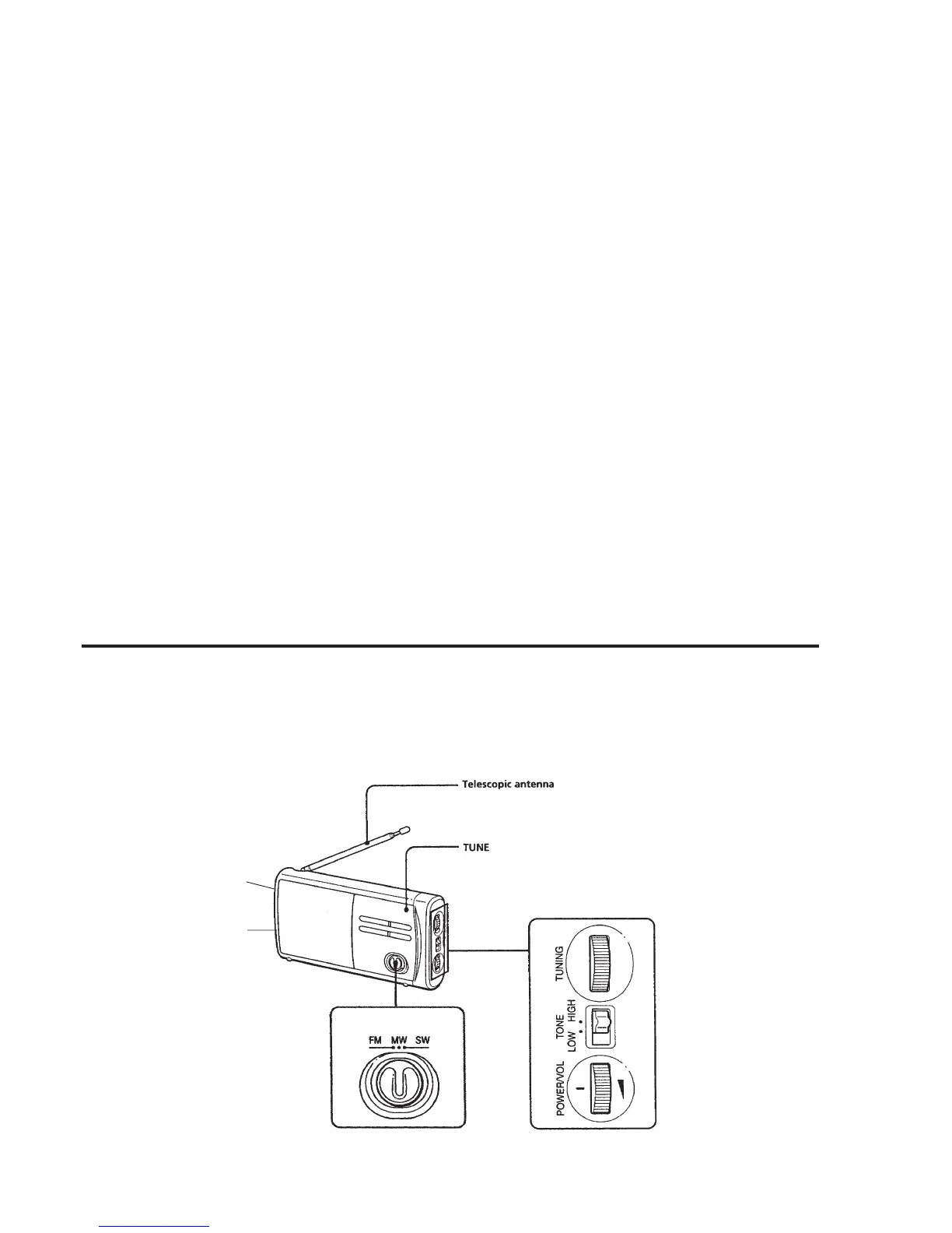
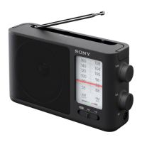
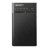
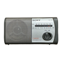
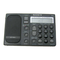
Location and Function of Controls .................................... 2
2. DISASSEMBLY
2-1. Cabinet (Rear)............................................................. 3
2-2. Cabinet (Front) ........................................................... 3
2-3. Main Board, Chassis................................................... 4
3. DIAL POINTER INSTALLATION ........................... 5
4. ELECTRICAL ADJUSTMENTS............................. 6
5. DIAGRAMS
5-1. Printed Wiring Boards ................................................ 7
5-2. Schematic Diagram..................................................... 9
6. EXPLODED VIEWS ...................................................11
7. ELECTRICAL PARTS LIST ................................... 13
Flexible Circuit Board Repairing
• Keep the temperature of the soldering iron around 270°C during
repairing.
• Do not touch the soldering iron on the same conductor of the
circuit board (within 3 times).
• Be careful not to apply force on the conductor when soldering or
unsoldering.
Notes on chip component replacement
• Never reuse a disconnected chip component.
• Notice that the minus side of a tantalum capacitor may be dam-
aged by heat.
TABLE OF CONTENTS
SECTION 1
GENERAL
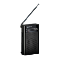
Earphone jack (@)
DC IN 4.5V
LOCATION AND FUNCTION OF CONTROLS