– 5 – – 6 –
SECTION 3
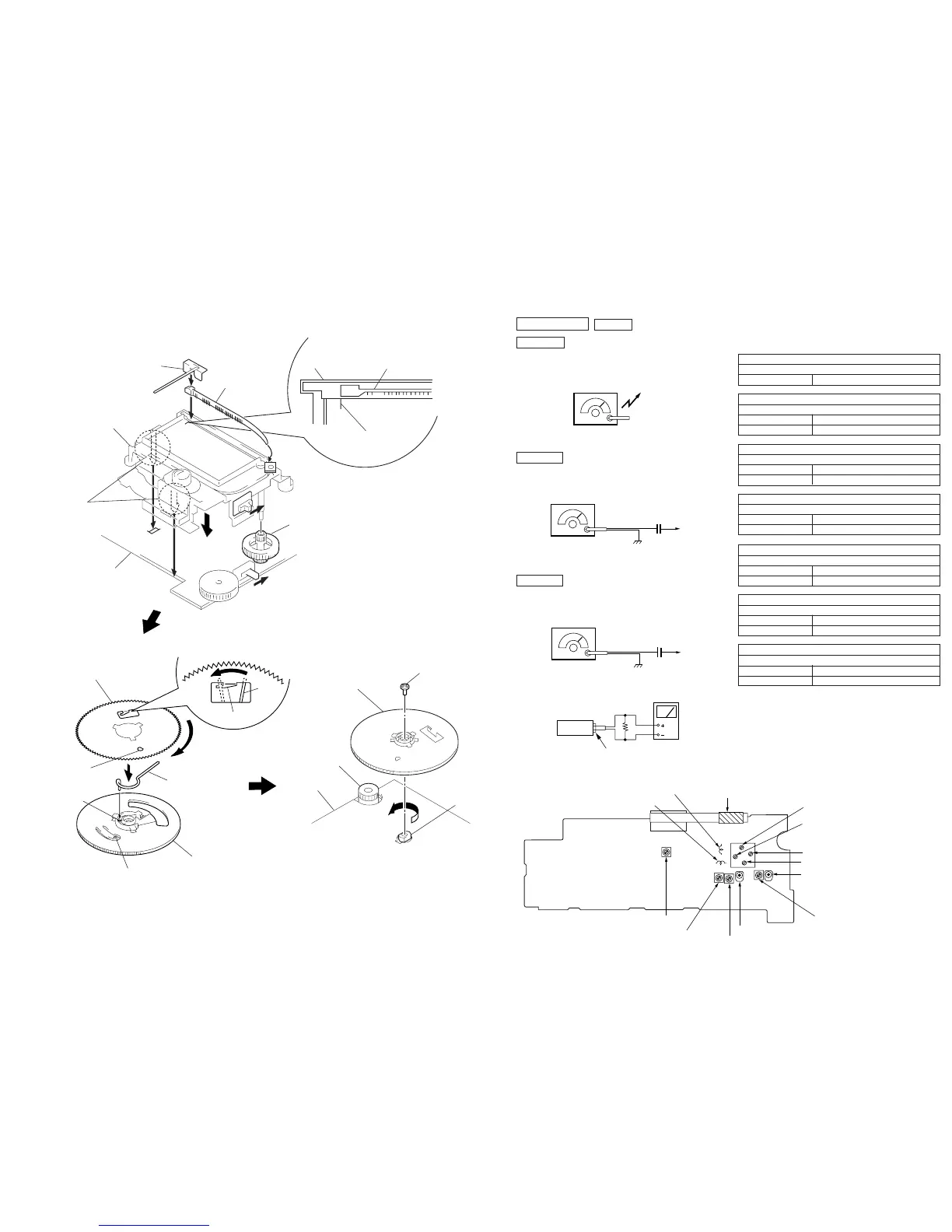
DIAL POINTER INSTALLATION
Note : Follow the installation procedure in the numerical order given.
1
Rack
6
Rack
5
Knob (tone)
5
3
Knob (tune)
2
Pointer
Chassis
Chassis
4
Scribed line
Claws
Main board
S2
1 Insert the rack into the chassis groove.
2 Install the pointer.
3 Install the knob (tune).
4 Slide the rack and align it with the groove on the scribed
line.
5 Align the knob (tone) and the S2.
6 Install the chassis to the main board.
1 Turn the CV shaft all thye way counterclockwise.
2 Set the gear ASSY onto the CV shaft in a
direction as a figure.
3 Secure the gear ASSY with screw.
Gear (A),tuning capacitor
4
2
1
3
Stopper
Spring
(gear)
Hole
A
Projection
Gear (B),tuning capacitor
B
Hole
Spring (gear)
3
Screw (1.7x3)
2
Gear ASSY
1
CV shaf
Main board
Knob (tune)
1 Put a point of spring (gear) in a hole of “gear (A), tuning
capacitor” and install it.
2 Install “gear (B), tuning capacitor” in a direction as a figure.
3 Turn the “gear (B), tuning capacitor” till a position of B fits
A.
4 Hang the spring (gear) with a stopper.
SECTION 4
ELECTRICAL ADJUSTMENTS
TUNER SECTION
MW Section
Procedure :
BAND : MW
SW Section
Procedure :
BAND : SW
FM Section
Procedure :
BAND : FM
AM RF signal
generator
30% amplitude modulation by 400Hz
signal.
Output level : as low as possible
Put the lead-wire
antenna close to
the set.
• Repeat the procedures in each adjustment several times, and the
frequency coverage and tracking adjustments should be finally
done by the trimmer capacitors.
< > : Saudi Arabia model
AM IF ADJUSTMENT
Adjust for a maximum reading on level meter.
T1 455kHz
MW FREQUENCY COVERAGE ADJUSTMENT
Adjust for a maximum reading on level meter.
L5 520kHz
CT4 1,650kHz
MW TRACKING ADJUSTMENT
Adjust for a maximum reading on level meter.
L1 620kHz
CT1 1,400kHz
SW FREQUENCY COVERAGE ADJUSTMENT
Adjust for a maximum reading on level meter.
L6 5.8MHz
CT6 18.5MHz
SW TRACKING ADJUSTMENT
Adjust for a maximum reading on level meter.
L2 5.8MHz
CT5 18.5MHz
FM FREQUENCY COVERAGE ADJUSTMENT
Adjust for a maximum reading on level meter.
L4 86.5MHz <87.35MHz>
CT3 109.5MHz <108.25MHz>
FM TRACKING ADJUSTMENT
Adjust for a maximum reading on level meter.
L3 86.5MHz <87.35MHz>
CT2 109.5MHz <108.25MHz>
L6 : SW Frequency Coverage Adjustment
CT3 : FM Frequency Coverage Adjustment
L4 : FM Frequency Coverage Adjustment
L5 : MW Frequency Coverage Adjustment
CT6 : SW Frequency Coverage Adjustment
CT4 : MW Frequency Coverage Adjustmen
T1 : AM IF Adjustment
L1 : MW Tracking Adjustment
CT1 : MW Tracking Adjustment
CT2 : FM Tracking Adjustment
CT5 : SW Tracking Adjustment
L2 : SW Tracking Adjustment
L3 : FM Tracking Adjustment
Adjustment Location : Main board (Component side)
AM RF signal
generator
12PF
30% amplitude modulation by
400Hz signal.
Output level : as low as possible
telescopi