EasyManua.ls Logo

Sony ICF-6500W Service Manual

Sony ICF-6500W
15 pages
To Next Page IconTo Next Page
Page #1 background imageLoading...
Page #1 background image
Frequency
range
Antennas
Speaker
Power
output
Outputs:
MICROFILM
CN
ae
ot
ae
Sy
ee
Me
Be
es
Saly
&
ite
Steen
ee
ee
_
FM/SW/MW
5BAND
RECEIVER
SPECIFICATIONS
FM
87.5-
108
MHz
SW,
3.9-
10
MHz
(77-
30m)
SW,
11.7-
20
MHz
(25.6-
15m)
SW,
20-28
MHz
(15-
10.7
m)
MW
530-
1,605
kHz
(566-
187
m)
SWI/FM:
Telescopic
antenna
SW/MW:
External
antenna
terminal
MW:
Built-in
ferrite
bar
antenna
Approx.
10cm
(4
inches)
dia.
1,100
mW
(at
10%
harmonic
distortion)
Earphone
jack
(minijack)
for
8-ohm
earphone
or
load
impedance
10
kilohms
or
higher
Recording
output
jack
(minijack)
output
level
1mV
(-—60
dB)
output
impedance
1
kilohm
Power
requirements
Battery
life”
Dimensions
Weight
9V
dc,
six
batteries
IEC
designation
R14
(size
C)
|
120
V
ac,
60Hz
with
supplied
Sony
AC-160W
ac
power
adaptor
12V
car
battery
with
optional
Sony
DCC-120
car
battery
cord
Approx.
24
hours
using
Eveready
No.
1235
Heavy
Duty
batteries
Approx.
289
x
168.5
=x
102mm
(wi/h/d)
(114,
x
6%,
x
44,
inches)
incl.
projecting
parts
and
controls
Approx.
1.85kg
(4
Ib
144,
02)
incl.
batteries
®@
SERVICE
MANUAL
Question and Answer IconNeed help?

Do you have a question about the Sony ICF-6500W and is the answer not in the manual?

Sony ICF-6500W Specifications

General IconGeneral
TypeRadio Receiver
Tuning SystemAnalog
Frequency Range (AM/MW)530 - 1600 kHz
Frequency Range (FM)87.5 - 108 MHz
Power SourceAC or Battery
DC Power6 V DC
Power Output1.5 W
Battery4 x D
AC Power120V AC
SpeakerBuilt-in

Summary

Receiver Specifications

Section 1: Diagrams

1-1. Mounting Diagram - Main Board

Component layout on the main board's conductor side.

Replacement Semiconductor Components

List and visual representation of key semiconductor parts.

Section 1: Diagrams - Part 2

Circuit Board Diagrams

Diagrams for Volume, Main, and Switch boards.

Section 1: Schematic Diagrams

Main Board Schematic Diagram

Detailed schematic for the main electronic circuitry.

Switch Board Schematic

Schematic details of the switch board assembly.

Exploded Views and Parts List

Exploded View 2-1

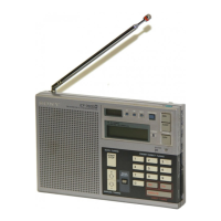
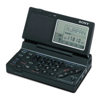
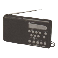
Visual breakdown of the receiver's external and internal components.

Exploded View 2-2

Detailed illustration of the internal mechanism and sub-assemblies.

Exploded View 2-3

Illustration of tuning and drive mechanism components.

Parts List - General Section

General Section Components

Detailed list of general mechanical and structural parts.

Accessory and Packing Materials

List of included accessories and packing materials.

Parts List - Electrical Components

Electrical Components List

List of electronic parts including ICs, diodes, capacitors, and filters.

Parts List - Electrical (Coils, Switches, Semiconductors)

Electrical Parts - Switches, Resistors, and Oscillators

List of switches, variable resistors, and crystal oscillators.

Related product manuals