Do you have a question about the Sony ICF-860L and is the answer not in the manual?
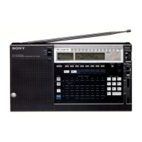
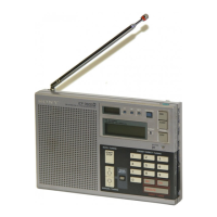
Introduces the ICF-860L, notes relation to ICF-850L, and lists key components.
Details frequency range, antennas, speaker, power, battery life, dimensions, and weight.
Highlights dual power sources, tone control, and fast tuning.
Step-by-step guide for stringing the dial cord.
Instructions for installing the dial pointer correctly.
Covers FM frequency coverage and tracking adjustments.
Details adjustments for MW, LW, and SW bands, including frequency coverage and tracking.
Illustrates the physical placement of components on the main board.
Shows the pin configurations for key semiconductors.
Detailed illustration of mechanical parts and their assembly.
Lists part numbers and descriptions for various components.
Detailed circuit diagram of the main board.
Circuit diagram for the power supply board.
Lists specific values and types for capacitors, resistors, and coils.
Lists semiconductors, transformers, switches, and other electronic components.