Do you have a question about the Sony ICF-2001D and is the answer not in the manual?
Details the receiver's circuit configuration.
Lists operational frequency bands for different models.
Describes the antenna types used for reception.
Outlines power sources and requirements for operation.
Provides estimates for battery operational duration.
Highlights critical components for safe operation.
Overview of the receiver's band coverage and tuning system.
Details on tuning methods, memory storage, and timers.
Information on using batteries, AC, or car battery power.
How different models are identified by LCD plates.
Instructions to prevent fire or electrical shock hazards.
Specific instructions for UK customers regarding mains lead wiring.
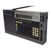
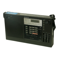
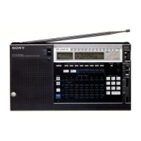
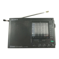
Introduces controls, lists primary functions, and references photos.
Detailed descriptions of power, timer, light, and display-related controls.
Detailed descriptions of band selection, AM modes, and tuning controls.
Detailed descriptions of memory, scanning, and indicator controls.
Covers manual tune mode, RF gain, tone, volume, enter, and direct tuning.
Describes antenna, stand, battery compartment, and power input jacks.
Explains advanced uses of memory preset keys, like scan range checks.
Installation, life, replacement, and notes for clock batteries.
Information on using radio batteries, AC adapter, and car battery.
Steps for setting the clock and changing the display format.
How to input frequencies directly for station tuning.
Details on inputting frequencies, including special cases and error indications.
Explains manual tuning and the tune mode selector.
Guidance on adjusting antennas for FM, SW, MW, and LW reception.
How to choose WIDE, NARROW, SYNC, USB, or LSB/CW modes.
Instructions for using synchronous detection to reduce interference.
How to scan, memorize stations, and check memory contents.
Procedure to set the MW scanning interval to 9 kHz or 10 kHz.
Explains DEFINE scan and broadcast band scan modes.
Lists broadcast bands and their frequency ranges for scanning.
Step-by-step guide to memorizing stations into presets.
How memory scan tuning works and how to start/stop it.
How to use the skip mark to exclude stations/bands from memory scanning.
How to set and use the sleep timer to turn off the receiver automatically.
Explains error codes that may appear during sleep timer operation.
Detailed steps for setting turn-on time, duration, and station.
How to check, cancel, or set operation time to zero.
How to connect external antennas for FM and AIR reception.
Guidance for connecting external antennas for SW and MW/LW bands.
A high-level schematic showing the main functional blocks of the receiver.
Addresses issues like no display, dim display, no sound, and poor reception.
Solutions for frequency input, scanning, and memory tuning failures.
Troubleshooting for programmable timer issues and error messages.
Steps to remove the rear cabinet and access internal components.
Instructions for lifting and unlocking main boards for access.
Steps for disconnecting boards, knobs, and lifting the chassis.
Procedures for removing the LCD indication plate and its associated parts.
Steps to reconnect flexible boards and external power supplies.
Steps for removing and reassembling the keyboard and rotary encoder.
Instructions for removing screws and reassembling the LCD plate and cabinet.
Steps to unsolder shield plates, remove screws, and disconnect rubber connectors.
Guides for installing the power knob and S.F.L. knob, including IC601.
Procedure to adjust the timer-clock frequency using a counter.
Steps for adjusting synchronous detection for optimal AM reception.
Procedure to adjust PLL1 frequency for FM band reception.
Procedure to adjust VCO2 freerun frequency for AM band.
Procedure for adjusting VC01 frequency and tracking for AM band.
Steps for aligning the AM first IF stage for optimal performance.
Procedure for aligning the AM/AIR 455kHz IF stage.
Procedure to check the AM/AIR 2nd local oscillator frequency.
Steps for aligning the FM IF stage for maximum signal output and minimum distortion.
Procedure for adjusting FM tracking for optimal reception across bands.
Procedure for adjusting AIR tracking for optimal reception.
Table detailing DC voltages at various points under different AM band modes.
Visual representations of signal waveforms at various points in the circuit.
Visual representations of signal waveforms at various points in the circuit.
Visual representations of signal waveforms at various points in the circuit.
Visual representations of signal waveforms at various points in the circuit.
Visual representations of signal waveforms at various points in the circuit.
Visual representations of signal waveforms at various points in the circuit.
Diagram showing segments and commons of the LCD panel driven by ICs.
Diagrams showing lead layouts for various semiconductors.
Identifies critical components for safety and replacement.
Notes on stocking, typical circuits, and components identified by shading.
Lists accessories like adapters, manuals, and packing materials.
Specific modifications required when replacing IC4 or IC6 with new types.
| Memory | 32 presets |
|---|---|
| Bands | LW, MW, SW, FM |
| Modes | AM, FM, SSB |
| Type | Portable Receiver |
| Tuning Steps | 1 kHz (AM), 5 kHz (FM) |
| Frequency Range | 150 kHz - 29999 kHz (LW, MW, SW), 76 MHz - 108 MHz (FM) |