Do you have a question about the Sony ICF-22 and is the answer not in the manual?
List of general mechanical and external parts.
List of electronic components like knobs, speakers, and antennas.
List of included accessories and packing materials.
Details on frequency range, antennas, power output, and dimensions.
Critical safety information regarding component replacement.
Steps for preparing the silkworm gut for the dial cord.
Instructions for stringing the silkworm gut through the mechanism.
Instructions for tuning and aligning the AM band reception.
Details on tracking and frequency coverage adjustments for AM.
Procedure for adjusting FM band tracking for optimal signal.
Procedure for adjusting FM band frequency coverage.
Electrical schematic of the main circuit board components.
Electrical schematic of the jack board and external connections.
Visual breakdown of internal and external parts with numbering.
Numerical reference to parts listed in the manual.
Detailed list of general mechanical parts and their numbers.
List of included accessories, manuals, and related items.
List of capacitors, coils, and their specifications.
List of semiconductors, resistors, transformers, and switches.
This document provides service and operational information for the Sony ICF-22/22L and ICF-25/25L portable radio receivers. These models are designed for receiving broadcast signals across multiple frequency bands, offering users a versatile listening experience. The manual details various aspects of the device, from its basic function to intricate maintenance and adjustment procedures, ensuring comprehensive support for both users and service technicians.
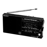
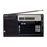
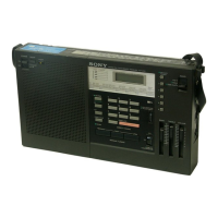
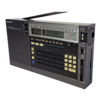
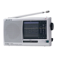
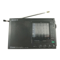
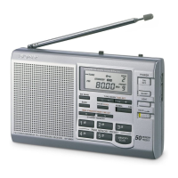
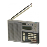
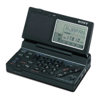
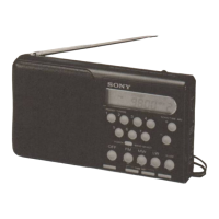
The primary function of these devices is to receive and reproduce radio broadcasts. The ICF-22/22L models are 3-band receivers, with the ICF-22 supporting FM/MW/SW (Frequency Modulation, Medium Wave, Short Wave) and the ICF-22L supporting FM/MW/LW (Long Wave). The ICF-25/25L models also offer 3-band reception, with the ICF-25L specifically designed for FM/MW/LW. This multi-band capability allows users to tune into a wide range of radio stations, from local FM broadcasts to international shortwave transmissions or longwave signals, depending on the specific model and region. The devices are designed for portability, making them suitable for use in various environments, both indoors and outdoors.
Key usage features of these receivers include their intuitive controls and robust design. The devices are equipped with a telescopic antenna for FM reception and a built-in ferrite bar antenna for MW/LW reception, optimizing signal capture across different bands. A speaker is integrated for direct audio output, and an earphone jack (minijack) is provided for private listening. Power can be supplied via batteries, offering portability, or through an external DC power source, allowing for extended use without battery drain. The ICF-25L, for instance, highlights "Fast tuning to key stations marked on the MW and LW dial scales," indicating a user-friendly design for quick station access. The inclusion of a "one chip IC (Integrated Circuit)" is noted as contributing to "High selectivity and high sensitivity," which translates to better reception quality and a more enjoyable listening experience for the user. The presence of a carrying handle, as mentioned in the specifications for the ICF-25L, further enhances its portability and ease of use.
From a maintenance perspective, the service manual provides detailed instructions for various adjustments and repairs. The "Parts List" section, for example, enumerates both general and electrical components, complete with part numbers and descriptions. This is invaluable for identifying and ordering replacement parts, ensuring the longevity of the device. General components include items like tuning knobs, volume knobs, speaker nets, and cabinet assemblies, which are prone to wear and tear or accidental damage. Electrical parts range from the telescopic antenna and PC board assemblies to ceramic capacitors, coils, resistors, and the speaker itself, covering the core electronic functionality.
A significant portion of the manual is dedicated to "Adjustments," which are critical for maintaining optimal performance. For the AM section (MW/LW), procedures like "MW Tracking Adjustment," "LW Tracking Adjustment," "IF Alignment," "MW Frequency Coverage Adjustment," and "LW Frequency Coverage Adjustment" are outlined. These adjustments involve using a VTVM (Vacuum Tube Voltmeter) and an AM RF SG (Radio Frequency Signal Generator) to fine-tune the receiver's circuitry for maximum signal strength and accurate frequency coverage. Similarly, for the FM section, "FM Tracking Adjustment" and "FM Frequency Coverage Adjustment" are detailed, requiring an FM RF SG and a VTVM to ensure precise tuning and optimal FM reception. These procedures often involve adjusting specific coils (L1, L2, L3, L4, L7) and trimmer capacitors (CT1, CT2, CT3, CT4, CT5, CT6), highlighting the intricate nature of radio alignment.
The manual also includes "Mounting Diagrams" and "Schematic Diagrams," which are essential for service technicians. The mounting diagrams illustrate the physical layout of components on the main board and jack board, aiding in component identification and replacement. The schematic diagrams provide a detailed electrical representation of the circuitry, showing connections between components, voltage points, and signal paths. This information is crucial for troubleshooting and diagnosing electrical faults. Notes within the schematic diagrams clarify capacitor values, resistor types, and voltage measurements, further assisting in repair. The "Dial Cord Stringing" section, with its detailed steps for "Silkworm Gut Preparation" and "Silkworm Gut Stringing," along with "Dial Cord Preparation" and "Dial Cord Stringing" for the tuning mechanism, addresses a common mechanical maintenance task, ensuring smooth and accurate tuning. The "Pointer Installation" instructions further complement this, ensuring the dial pointer aligns correctly with the tuned frequency.
A critical safety warning is prominently featured, stating that "Components identified by shading and mark ▲ on the schematic diagrams and in the parts list are critical to safe operation. Replace these components with Sony parts whose part numbers appear as shown in this manual or in supplements published by Sony." This emphasizes the importance of using genuine parts for safety-related components, ensuring the device operates without risk. The manual also clarifies that "mechanical parts with no reference number in the exploded views are not supplied" and that "items marked '*' are not stocked since they are seldom required for routine service," providing practical information for parts procurement. Overall, this service manual serves as a comprehensive guide for understanding, operating, and maintaining the Sony ICF-22/22L and ICF-25/25L radio receivers, ensuring their reliable performance over time.
| Tuning | Analog |
|---|---|
| Tuning Bands | AM, FM |
| Frequency Range (FM) | 87.5 - 108 MHz |
| Frequency Range (AM) | 530 - 1605 kHz |
| Headphone Jack | Yes |
| Power Source | 2 x AA batteries |
| Speaker | Built-in |