Do you have a question about the Sony ICF-7600D and is the answer not in the manual?
Details circuit system, frequency range, antennas, speaker, power output, and requirements.
Highlights critical components identified by shading for safe operation and replacement.
Identifies different model variants (AEP, UK, E, ME, French) and their specific frequency ranges.
Provides instructions for adjusting frequency range and replacing buttons.
Explains the structure of MELF components and how to read their color codes.
Details dimensions and identification for resistors, capacitors, transistors, and diodes.
Outlines procedures for removing and connecting chip components with precautions.
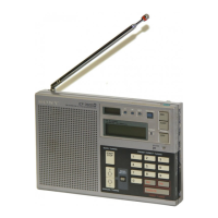
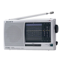
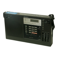
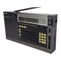
Describes controls on the front panel including indicators, power, tuning, and display.
Details fine tuning, AM mode, tone, volume, sensitivity, jacks, and time settings.
Presents the overall block diagram of the ICF-7600D receiver circuitry.
Details the terminal functions of IC201 and the key matrix input/output mapping.
Provides steps for disassembling the rear and front cabinets, and the jack board.
Details the procedures for removing the switch board and the main board.
Covers PLL frequency check and electrical adjustments for various circuits.
Details alignment procedures for AM IF, AM 2nd IF VCXO, and FM IF circuits.
Provides instructions for adjusting the FM tracking for optimal reception.
Presents mounting diagrams showing component placement on various boards.
Provides detailed schematic diagrams for the receiver's electronic circuits.
Shows conductor side mounting layouts for the antenna, main, and jack boards.
Presents detailed circuit schematics covering various sections of the receiver.
Lists electrical parts including capacitors, inductors, filters, and switches.
Lists electrical parts including resistors and semiconductors.
Lists electrical parts including transformers, ICs, jacks, and other components.
| Frequency Range FM | 76 - 108 MHz |
|---|---|
| Frequency Range SW | 1.6 - 30 MHz |
| Power Source | 4 x AA batteries or AC adapter |
| Speaker | Built-in |
| Headphone Jack | Yes |
| Antenna | Telescopic |
| Type | Portable Receiver |