Do you have a question about the Sony ICF-7601 and is the answer not in the manual?
Details the technical specifications of the ICF-7601/7601L radio models.
Guidance on battery life and using the HOLD switch for convenient operation.
Provides notes on flexible circuit board repair and chip component replacement.
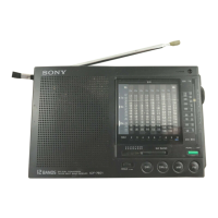
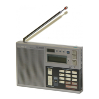
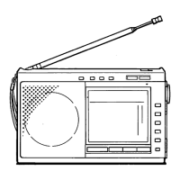
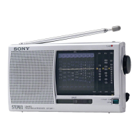
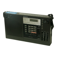
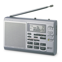
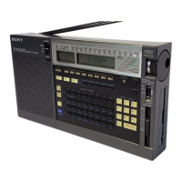
Details the location and function of all controls and indicators on the radio.
Procedures for MW IF, frequency coverage, and tracking adjustments.
Procedures for FM IF, frequency coverage, and tracking adjustments.
Procedures for SW band IF, frequency coverage, and tracking adjustments.
Diagrams showing the physical location of adjustment components.
Illustrates the functional blocks and signal flow of the radio.
Detailed schematic diagrams of the radio's electronic circuits.
Details the function and pin assignments of the µPD65005C IC.
Illustrates the physical lead configurations for various semiconductors.
Table mapping semiconductor reference numbers to their physical locations on the PCB.
Details the settings for various switches on the radio.
Provides notes on components, signal paths, and voltage measurements.
Details the function and settings of various switches on the radio.
An exploded view of the radio's general assembly with part numbers.
An exploded view of the radio's mechanism section with part numbers.
List of capacitors and resistors with their part numbers and specifications.
List of semiconductors with their part numbers and types.
List of filters, variable capacitors, and coils with part details.
List of diodes and ICs with their part numbers and specifications.
List of transformers, crystals, resistors with part details.
List of switches, connectors, and packing materials.