ICF-C490
99
Note on Printed Wiring Board:
• X : parts extracted from the component side.
• W : indicates side identified with part number.
•
f
: internal component.
• : Pattern from the side which enables seeing.
(The other layers' patterns are not indicated.)
4-2. NOTE FOR PRINTED WIRING BOARDS AND SCHEMATIC DIAGRAM
Note on Schematic Diagram:
• All capacitors are in µF unless otherwise noted. pF: µµF
50 WV or less are not indicated except for electrolytics
and tantalums.
• All resistors are in Ω and
1
/
4
W or less unless otherwise
specified.
•
f
: internal component.
• C : panel designation.
• IC Block Diagrams
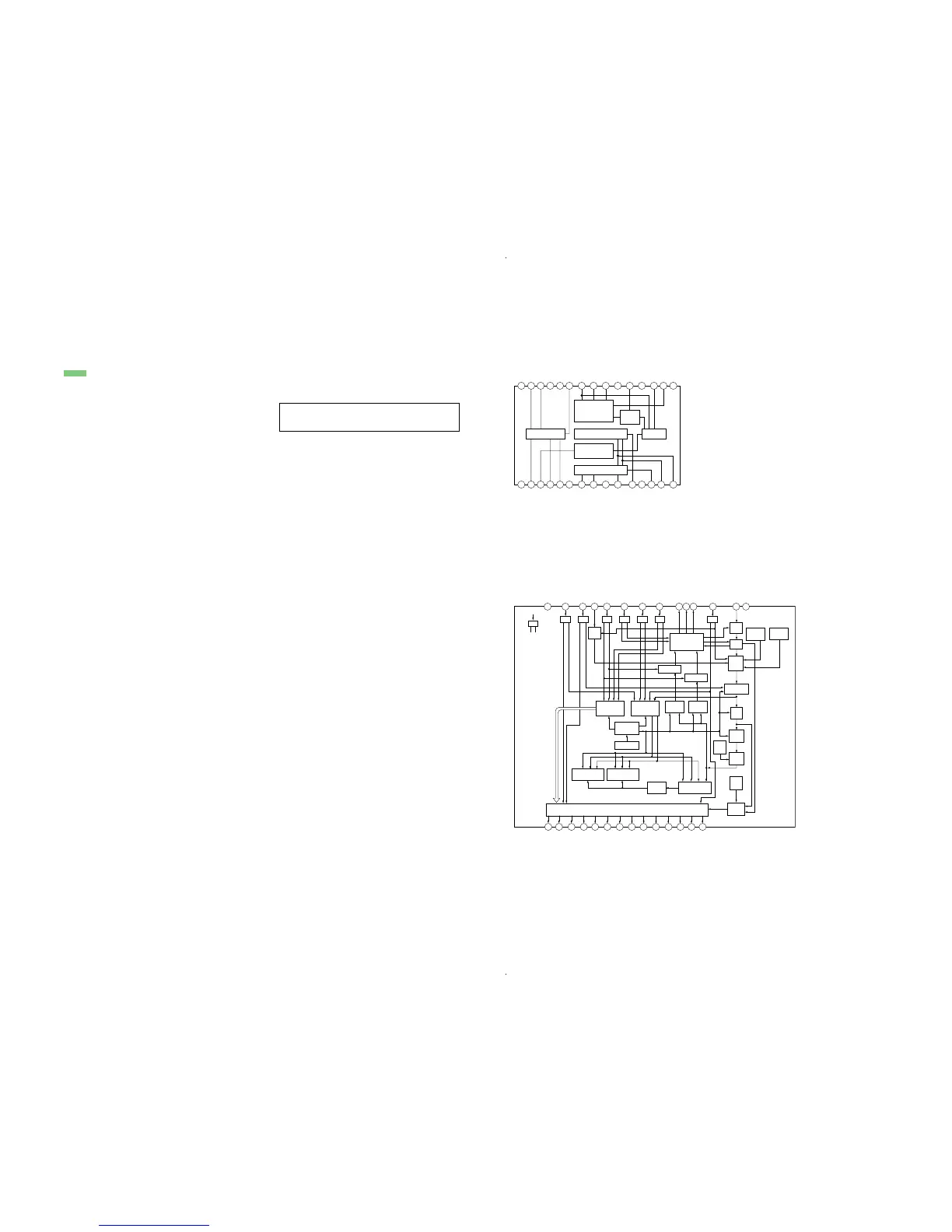
IC1 CXA1019S
1
2 3
4
5 6 7 8 9
10
15141312
11
FM
DISCRIMINATOR
AF POWER AMP AM FE FM IF
TUNING
METER
AM IF DET AGC
FM FE
23 22 21 202425 19 18 17 1629 28 27 2630
GND
GND
AF OUT
VCC
RIPPLE
FILTER
AF IN
DET OUT
AFC AGC
AFC AGC
IF GND
METER
N.C
FM IF IN
AM IF IN
FM/AM BAND
SELECT
FM/AM
IF OUT
FE GND
N.C
AM RF IN
FM RF
REG OUT
FM OSC
FM RF IN
AFC
AM OSC
VOL
NF
FM DISCRI
GND
GND
Note: The components identified by mark 0 or dotted line
with mark 0 are critical for safety.
Replace only with part number specified.
• A : B+ Line.
• H : adjustment for repair.
•Voltages are dc with respect to ground in no-signal
(detuned) conditions.
no mark : FM
(): AM
•Voltages are taken with a VOM (Input impedance 10 MΩ).
Voltage variations may be noted due to normal produc-
tion tolerances.
• Signal path.
F : FM
f : AM
IC101 LM8562
28 27 26 25 20 19 18 17 16 15
1 2 3 4 5 6 7 8 9 10 11 12 13 14
AM & 10
,
S
HR AG & DE
PM & 10
,
S HR B
10
,
S HR C & HR E
10
,
S MIN A & F
10
,
S MIN B & G
10
,
S MIN C & D
MIN A & F
COLON OUTPUT
MIN C & D
MIN B & G
10
,
S MIN E
& MIN E
HR B & G
HR C & D
HR A & F
TIME SET INPUT
VDD
VSS
SLEEP/SNOOZE
RT-TIME
SET/DIMMER
MODE
SELECT
50/60Hz
INPUT
ON/OFF INPUT
ALM DISP SELECT
ALM-2 OUTPUT
ALM-1 OUTPUT
RADIO OUTPUT
SPEED/
POWER DOWN
CR OSC
DISPLAY DECODER/DRIVER
T T T T
OUTPUT
CONTROL
DISPLAY
CONTROL
PWR UP
INPUT
CONTROL
ALARM 1 CTR ALARM 2 CTR
TIME CTR
TIME
SET
BLANK
FLASH
SLEEP
CTR
SNOOZE
CTR
STAND
BY DET
OSC
CTR
GATE
1/2
GATE
PF.
DET
SEC
CTR
1/25 or 1/30
INNER
OSC
CONTROL
GATE
COMP.
CONTROL
RESET
CONTROL
T
T
T T
24 23 22 21
ON
OFF
50/60 SEL
12/24 SEL
SEC,TIME,ALARM 1/2,SLEEP
RESET
U/D
SET CK
DIMMER
RT-SET
2Hz
1Hz
RESET
THREE
INPUT
CIRCUIT