33
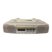
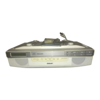
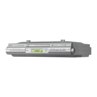
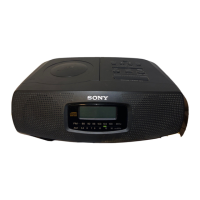
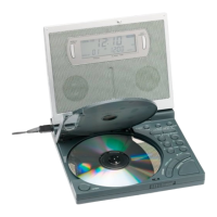
ICF-CD543RM
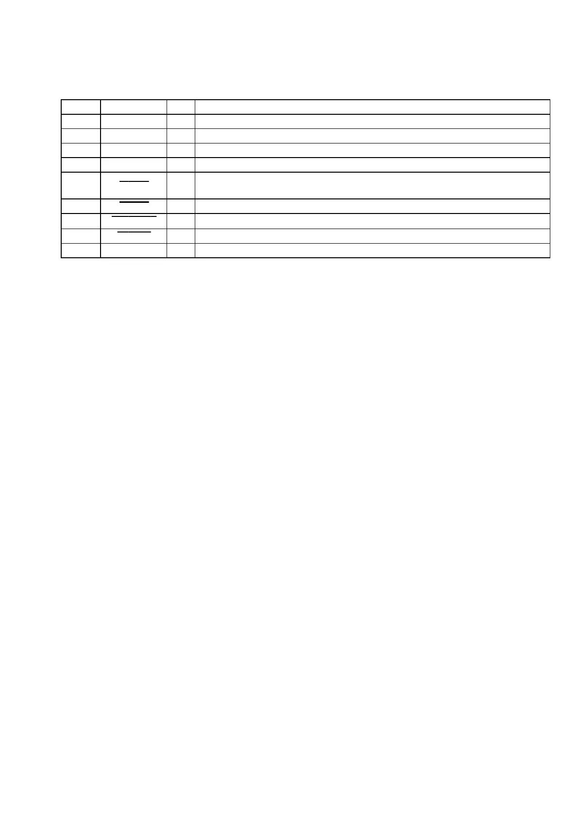
Pin No. Pin Name I/O Description
72 VDD0 — Power supply terminal (+3.3V)
73 VSS0 — Ground terminal
74 X1 I Main system clock input terminal (4.19 MHz)
75 X2 O Main system clock output terminal (4.19 MHz)
76 RESET I
System reset signal input “L”: reset
For several hundreds msec. after the power supply rises, “L” is input, then it changes to “H”
77 CD ON O Power on/off control signal output for the CD +3.3V power supply “L”: CD power on
78 RADIO ON O Power on/off control signal output for the radio +3.3V power supply “L”: radio power on
79 A MUTE O Audio line muting on/off control signal output “L”: muting on
80 KITCHEN LED
O LED drive signal output of the TIMER “L”: LED on
 Loading...