32
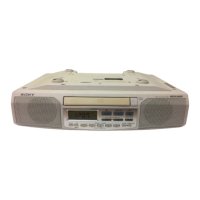
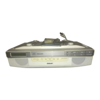
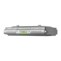
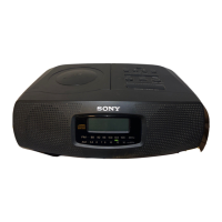
ICF-CD543RM
5-12. IC PIN FUNCTION DESCRIPTION
• LCD BOARD IC401 µPD789477GC-A16-8BT (SYSTEM CONTROLLER)
Pin No. Pin Name I/O Description
1, 2 NC
— Not used
3 to 5 VLC0 to VLC2 —
Terminal for doubler circuit capacitor connection to develop liquid crystal display drive voltage
6 to 9 COM0 to COM3 O Common drive signal output to the liquid crystal display
10 to 25 SEG0 to SEG15 O Segment drive signal output to the liquid crystal display
26 to 32
NC
— Not used
33 OPEN S/W I
Detection input from the tray open/close detect switch
“L”: when tray is open, “H”: when tray is close
34 CLOSE S/W
I
Detection input from the tray open/close detect switch
“L”: when tray is close, “H”: when tray is open
35
TRAY OPEN O Motor drive signal output to the disc tray open/close motor driver “H” table out
36
TRAY CLOSE O Motor drive signal output to the disc tray open/close motor driver “H” table in
37 NC
— Not used
38 AVDD — Power supply terminal (+3.3V) (analog system)
39
ENCODE + I Jog dial pulse input terminal
40
ENCODE – I Jog dial pulse input terminal
41 OPTION I Destination setting terminal Not used
42 to 44 KEY0 to KEY2
I Key input terminal (A/D input)
45
RST
— Not used
46 DRF I Focus on/off detection signal input from the digital signal processor
47 AVSS — Ground terminal (analog system)
48 RC I
Remote control signal input from the remote control receiver
49 AC IN I Power failure detection signal input terminal “L”: power failure, “H”: power on
50 WRQ I Interruption detection signal input from the digital signal processor
51 FSEQ I Synchronizing signal detection signal input from the digital signal processor
52 BUZZER O Buzzer sound drive signal output
53 C LAT O Chip enable signal output to the digital signal processor
54 C DATA O Serial data output to the digital signal processor
55 C CLK O Serial data transfer clock signal output to the digital signal processor
56 C DATA IN I Serial data input from the digital signal processor
57 XRST O Reset signal output to the digital signal processor “L”: reset
58 VR DATA O Volume data output
59 VR CLOCK O Volume clock signal output
60 POWER ON O Power amplifier on/off control signal output “L”: standby mode, “H”: power amplifier on
61 R DATA O Serial data output terminal Not used
62 R CLK O Serial data transfer clock signal output to the FM/AM PLL
63 R DATA IN I Serial data input from the FM/AM PLL
64 R CE O Chip enable signal output to the FM/AM PLL
65
TRAY MUTE
O Not used
66
NC
— Not used
67
SHIFT 0
— Not used
68
SHIFT 1
— Not used
69 IC — Internal connection terminal
70 TX1 I Sub system clock input terminal (32.768 kHz)
71 TX2 O Sub system clock output terminal (32.768 kHz)
 Loading...