KLV-32L500A
KLV-32L500A
39
NOTE: The components identifi ed by shading
and
!
mark are critical for safety. Replace only
with part number specifi ed.
NOTE: The components identifi ed by a red outline and a mark contain
confi dential information. Specifi c instructions must be adhered to whenever
these components are repaired and/or replaced.
See Appendix A: Encryption Key Components in the back of this manual.
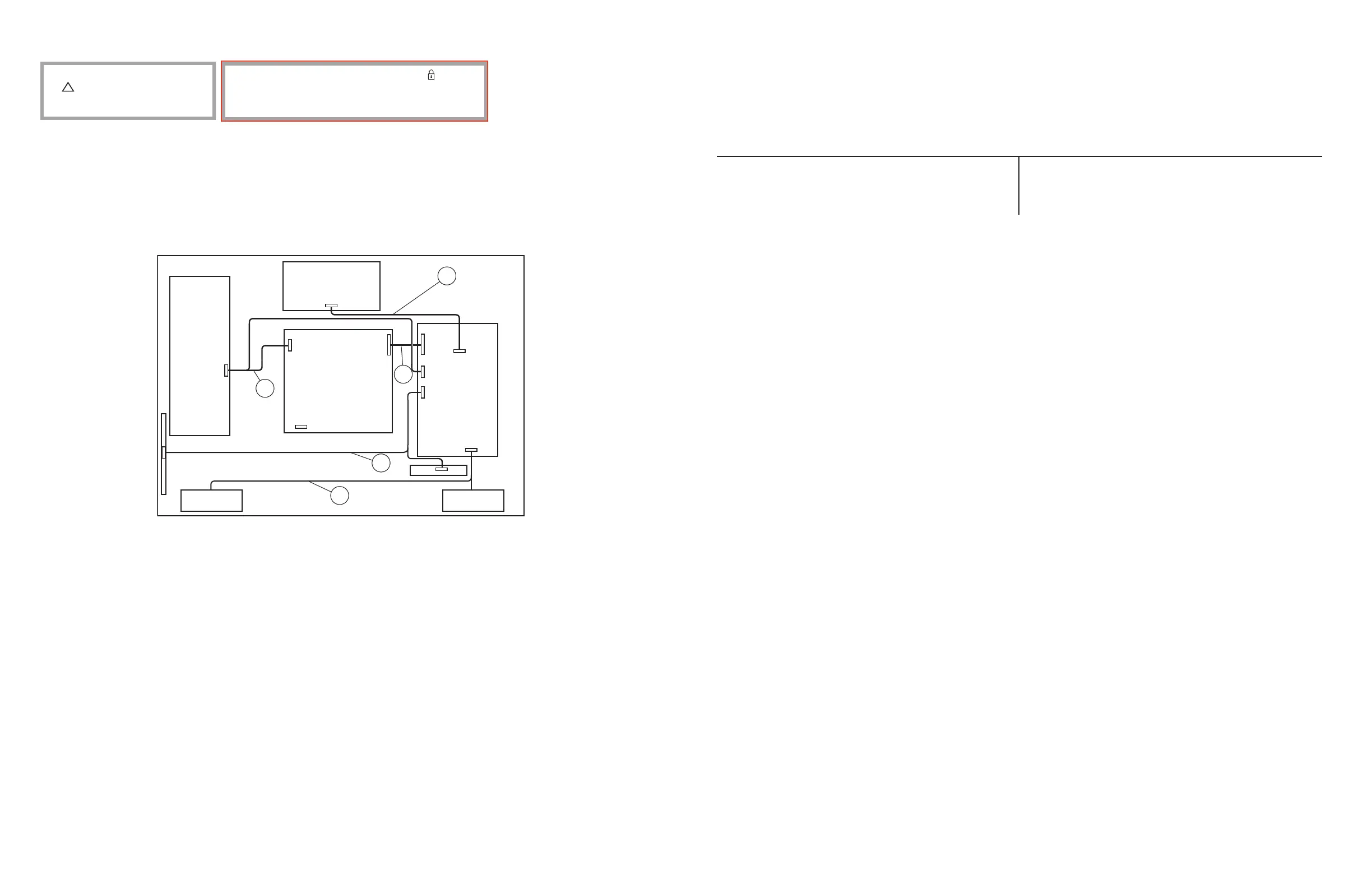
4-3. CONNECTORS
REF. NO. PART NO. DESCRIPTION [ASSEMBLY INCLUDES] REF. NO. PART NO. DESCRIPTION [ASSEMBLY INCLUDES]
101 1-836-564-21 (LVDS) LEAD WIRE WITH CONNECTOR
* 102 1-910-053-23 CONNECTOR ASSY 13P
* 103 1-910-053-22 CONNECTOR ASSY 10P
INV
POWER UNIT
T-CON
HT1
BT2
CN7001
CN7000
CN3001
CN3000
CN8001
CN6201 (GT3) CN6202 (GT3)
CN9100
SWITCH
UNIT
SP
SP
101
102
103
104
105
* 104 1-910-053-25 SP CONNECTOR ASSY 4P
* 105 1-910-053-24 CONNECTOR ASSY 14P
 Loading...