Do you have a question about the Sony KV-21FT1E and is the answer not in the manual?
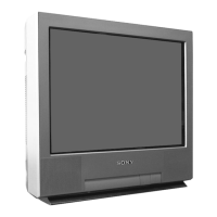
| Screen Size | 21 inches |
|---|---|
| Display Type | CRT |
| Aspect Ratio | 4:3 |
| TV Standard | PAL/SECAM |
| Audio Output | Mono |
| Inputs | SCART, RF |
Details the pin configuration and signal levels for the 21-pin connector.
Lists error messages, LED codes, and steps to enter the self-diagnostic mode.
Guides initial TV setup and automatic channel tuning process.
Explains how to navigate and utilize the on-screen menu for TV settings.
Instructions on how to use Teletext, including page selection and Fastext.
Instructions for connecting external devices like VCRs and decoders to the TV.
Provides solutions for common picture and sound problems encountered with the TV.
Step-by-step guide for safely removing the TV's rear cover and chassis assembly.
Detailed steps for safely removing the CRT picture tube, including anode cap handling.
Procedure for aligning the electron beams for optimal picture geometry and color purity.
Adjusting static convergence using H.STAT and V.STAT controls for precise color alignment.
Adjusting various geometry parameters like pin, size, and linearity for optimal picture display.
Adjusting the flyback transformer focus control for sharp picture clarity.
Adjusting G2 control and white balance for optimal picture brightness and color accuracy.
Performing electrical adjustments using the remote commander in the service mode.
Details the functions and access methods for Test Mode 2 for advanced diagnostics.
Identifies the physical locations of main circuit boards within the TV chassis.
Provides schematics and wiring diagrams for understanding circuit layout and connections.
Visual representation of the TV's internal circuit blocks and their interconnections.
List of semiconductor components used in the TV, including part numbers.
Illustrates the internal functionality and pin assignments of important ICs.
Diagram showing the main chassis components and their assembly order.
Detailed breakdown of the picture tube and associated parts, including deflection yoke and magnets.
List of common parts for the A Board, applicable across multiple models.
Lists parts specific to different model variants of the A Board.
Parts list for the complete C Board assembly.
List of miscellaneous items not categorized elsewhere, such as screws and wires.
List of included accessories and packaging materials for the TV unit.
Information on the TRACE software, its features, and necessary PC specifications for TV repair.