4-18 (E)
MAV-555
4-6-4. A/D Video Level Adjustment
Preparation
n
Check the following setup menus before starting adjust-
ment.
. Check the NTSC/PAL setup. (Refer to menu No. 010 of
Section 1-9-2 of the MAV-555 Installation Manual.)
. Check the network setup. (Refer to menu No. 220 of
Section 1-9-6 of the MAV-555 Installation Manual.)
Connection
4-6. AD-160 Board Adjustment
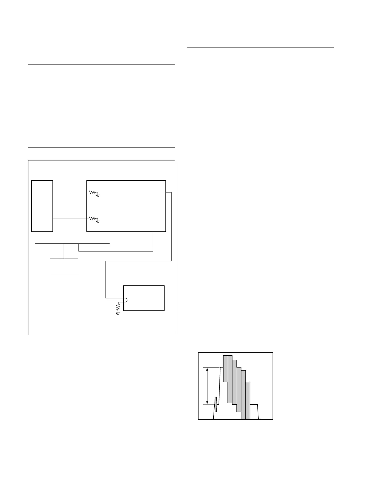
* : Connect to the VIDEO IN R1-IN or the VIDEO IN R2-IN in accor-
dance with the port to which the BKMA-511 is connected.
Signal
generator
RAMP
or
color bars
Black burst
VIDEO IN
*
(COMPOSITE)
R1-IN
or
R2-IN
REFERENCE
IN
MONITOR
OUT
ANALOG
COMP
ETHER
Waveform monitor
or an oscilloscope
Ethernet
PC
Monitor Output Level Check
n
Turn on the main power of the MAV-555 and measuring
equipment. Wait for at least 30 minutes of warm up before
starting any adjustments.
1. Set “782-INT VD SG” of the setup menu to “CB100”.
(Refer to Section 1-1-1.)
2. Set either “701-IN SETUP RMV P2” or “702-IN SET
UP RMV P2” to “off” on the setup menu in accor-
dance with the port that the BKMA-511 is connected
to. (Refer to Section 1-9-5 of the MAV-555 Installa-
tion Manual.)
3. Set “703-OUT SET UP P1” and “704-OUT SET UP
P2” to “off” on the setup menu. (Refer to Section 1-9-
5 of the MAV-555 Installation Manual.)
n
Keep the menus No. 701 (or 702), 703 and 704 until
all adjustments of the BKMA-511 are complete.
4. Turn the main power off and back on. Restart the
MAV-555.
n
To restart the MAV-555 quickly, execute “027-FAST
REBOOT” of the setup menu.
5. Press the R1 button on the PORT SELECT block of
the meter panel.
(Set so that the internal SG is output to the R1 port.)
6.
Press the COMPOSITE button of the VIDEO INPUT
SELECT block of the meter panel for at least three
seconds.
(The internal SG starts, and the COMPOSITE button
and the SDI button are turned on.)
7. Confirm that the following specifications are satisfied.
Specifications :
A = 714 ±7 mV (100 ±1 IRE) : 525/60 mode
A = 700 ±7 mV : 625/50 mode


 To Next Page