Do you have a question about the Sony MDS-S37 and is the answer not in the manual?
Details of the unit's input connectors and their specifications.
Details of the unit's output connectors and their specifications.
Voltage and frequency requirements for different regions.
Power usage details for various regions.
Part numbers for different regional models.
Method for checking AC leakage from exposed metal parts.
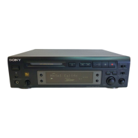
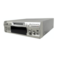
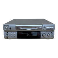
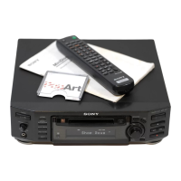
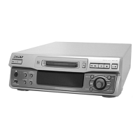
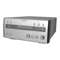
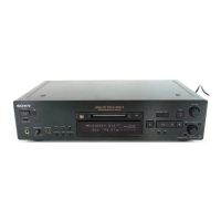
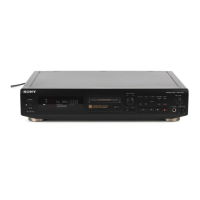
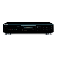
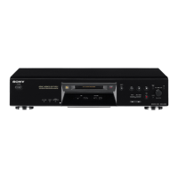
Identifies front panel controls and their functions.
Step-by-step guide for recording audio onto an MD.
Instructions for playing back audio from an MD.
Useful advice and techniques for recording audio.
How to monitor input signals before recording.
Procedure for overwriting previously recorded audio.
How to set optimal audio input levels for recording.
Methods for manually and automatically marking tracks.
Captures audio 2 seconds before recording starts.
Automatic recording sync with other audio equipment.
Dubbing CDs to MDs using CD synchro buttons.
How to view disc and track information on the display.
Techniques for finding specific tracks or points within tracks.
General notes and available editing functions.
Procedures for erasing tracks or entire discs.
How to divide, combine, move, and label tracks.
Explains audible feedback signals for various operations.
Information on digital copy restrictions.
Initial setup steps, including voltage selection.
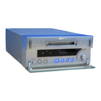
Steps to disassemble the front panel.
Steps to disassemble the main and back panels.
Steps to disassemble brackets (T, L, and R).
Steps to disassemble the BD board and sub chassis.
Steps to disassemble the shutter assembly and head.
Steps to disassemble the slider complete assembly.
Important safety and operational notes before entering test mode.
How to operate the continuous playback test mode.
How to operate the continuous recording test mode.
Mode for reading and writing non-volatile memory.
Functions of other buttons and meanings of test mode displays.
Safety and handling precautions for adjustments.
Procedure to create a disc for bias and error checks.
Steps to adjust the laser power output.
Procedure for adjusting the optical pickup traverse.
Steps to adjust focus bias for optimal performance.
Methods for checking error rates and focus bias.
High-level functional block diagrams of the unit.
Layout diagrams for BD, Main, and Panel boards.
Circuit schematics for BD, Main, and Panel sections.
Block diagrams and pinouts for key integrated circuits.
Diagram showing assembly of the unit's case.
Diagram showing assembly of the front panel components.
Diagrams showing assembly of the mechanism deck parts.
List of electronic components for the BD board.
List of electronic components for the Main board.
List of electronic components for the Panel board.
| Power Consumption | 15W |
|---|---|
| Supported Media | MiniDisc |
| Recording Format | ATRAC |
| Playback Format | ATRAC |
| Sampling Frequency | 44.1kHz |
| Digital Input | Optical |
| Analog Input | RCA |
| Analog Output | RCA |
| Remote Control | Yes |
| Total Harmonic Distortion | 0.005% |
| Type | MiniDisc Player |
| Audio Output | Analog, Digital |
| Channels | 2 |
| Wow and Flutter | Below measurable level |
| Output Level | 2V |