EasyManua.ls Logo

Sony MDS-JE520 Service Manual

Sony MDS-JE520
81 pages
To Next Page IconTo Next Page
Page #1 background imageLoading...
Page #1 background image
– 1 –
MICROFILM
MDS-JE520
SPECIFICATIONS
SERVICE MANUAL
MINIDISC DECK
— Continued on next page —
Model Name Using Similar Mechanism NEW
MD Mechanism Type MDM-5A
Optical Pick-up Type KMS-260A/J1N
US Model
Canadian Model
AEP Model
UK Model
E Model
Australian Model

Other manuals for Sony MDS-JE520

Question and Answer IconNeed help?

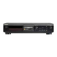
Do you have a question about the Sony MDS-JE520 and is the answer not in the manual?

Sony MDS-JE520 Specifications

General IconGeneral
Dynamic Range96 dB
Sampling Frequency44.1 kHz
Recording FormatATRAC
Playback FormatATRAC
Headphone OutputYes
TypeMiniDisc Player
Frequency Response5 Hz to 20 kHz
InputsOptical, Coaxial, Analog (RCA)
OutputsOptical, Analog (RCA)
Playback SystemATRAC
Wow and FlutterBelow measurable limit
Power SupplyAC 230V, 50/60Hz

Summary

SELF-DIAGNOSIS FUNCTION

Procedure for using the Self-Diagnosis Function (Error History Display Mode)

Details steps to use the error history display mode for servicing.

ITEMS OF ERROR HISTORY MODE ITEMS AND CONTENTS

Table of Error Codes

Lists and describes various error codes for the unit.

SAFETY-RELATED COMPONENT WARNING!!

SAFETY CHECK-OUT

LEAKAGE

Details checks for AC leakage from exposed metal parts to earth.

SECTION 1 SERVICING NOTE

LASER POWER METER

CHECKS PRIOR TO PARTS REPLACEMENT AND ADJUSTMENTS

FORCED RESET

Procedure to reset the system microprocessor.

RETRY CAUSE DISPLAY MODE

Reading the Track Mode Display

Basic Operations

Notes on Recording

Adjusting the Recording Level

Locating a Specific Track

Locating a Particular Point in a Track

Adjusting the analog signal level

Editing Recorded MDs

Erasing a Part of a Track (A-B Erase Function)

Dividing Recorded Tracks (Divide Function)

Combining Recorded Tracks (Combine Function)

Moving Recorded Tracks (Move Function)

Copying a track or disc title

Changing an existing title

Erasing a title on a disc (Name Erase)

Erasing all titles on a disc (Name All Erase)

Undoing the Last Edit (Undo Function)

SECTION 3 DISASSEMBLY

3-1. CASE AND FRONT PANEL

Procedure for disassembling the case and front panel.

3-3. BASE UNIT (MBU-5A) AND BD BOARD

3-4. SW BOARD AND LOADING MOTOR (M103)

SECTION 4 TEST MODE

4-1. PRECAUTIONS FOR USE OF TEST MODE

Important safety precautions before using the test mode.

4-5. SELECTING THE TEST MODE

4-5.1. Operating the Continuous Playback Mode

4-5.2. Operating the Continuous Recording Mode

4-5.3. Non-Volatile Memory Mode (EEP MODE)

4-6. FUNCTIONS OF OTHER BUTTONS

4-7. TEST MODE DISPLAYS

SECTION 5 ELECTRICAL ADJUSTMENTS

5-1. PARTS REPLACEMENT AND ADJUSTMENT

Flowchart for parts replacement and subsequent adjustments.

5-2. PRECAUTIONS FOR CHECKING LASER DIODE EMISSION

5-3. PRECAUTIONS FOR USE OF OPTICAL PICK-UP

5-4. PRECAUTIONS FOR ADJUSTMENTS

5-5. CREATING CONTINUOUSLY RECORDED DISC

5-6. CHECKS PRIOR TO REPAIRS

5-6-1. Temperature Compensation Offset Check

Procedure for temperature compensation offset check.

5-6-3. Traverse Check

Procedure for traverse check.

5-6-2. Laser Power Check

Procedure for laser power check.

5-6-4. Focus Bias Check

Procedure for focus bias check.

5-6-5. C PLAY Checking

Procedure for C PLAY check.

5-6-6. Self-Recording/playback Check

Procedure for self-recording/playback check.

5-7. INITIAL SETTING OF ADJUSTMENT VALUE

5-8. RECORDING AND DISPLAYING THE IOP INFORMATION

5-9. TEMPERATURE COMPENSATION OFFSET ADJUTMENT

5-10. LASER POWER ADJUSTMENT

5-11. TRAVERSE ADJUSTMENT

5-12. FOCUS BIAS ADJUSTMENT

5-13. ERROR RATE CHECK

5-13-1. CD Error Rate Check

Procedure for CD error rate check.

5-13-2. MO Error Rate Check

Procedure for MO error rate check.

5-14. FOCUS BIAS CHECK

5-15. AUTO GAIN CONTROL OUTPUT LEVEL ADJUSTMENT

5-15-1. CD Auto Gain Control Output Level Adjustment

Procedure for CD auto gain control adjustment.

5-15-2. MO Auto Gain Control Output Level Adjustment

Procedure for MO auto gain control adjustment.

5-15. ADJUSTING POINTS AND CONNECTING POINTS

SECTION 6 DIAGRAMS

6-2. BLOCK DIAGRAMS

WAVEFORMS

6-3. PRINTED WIRING BOARD - BD SECTION

6-4. SCHEMATIC DIAGRAM - BD SECTION - (1/2)

6-5. SCHEMATIC DIAGRAM - MAIN SECTION - (1/2)

6-6. PRINTED WIRING BOARD - MAIN SECTION

6-7. PRINTED WIRING BOARD - PANEL SECTION

6-8. SCHEMATIC DIAGRAM - PANEL SECTION

6-9. SCHEMATIC DIAGRAM – BD SWITCH SECTION

6-10. PRINTED WIRING BOARD – BD SWITCH SECTION

6-11. IC BLOCK DIAGRAMS

6-12. IC PIN FUNCTIONS

SECTION 7 EXPLODED VIEWS

SECTION 8 ELECTRICAL PARTS LIST

Related product manuals