EasyManua.ls Logo

Sony MDS-JE640 Service Manual

Sony MDS-JE640
66 pages
To Next Page IconTo Next Page
Page #1 background imageLoading...
Page #1 background image
MDS-JE640
SPECIFICATIONS
SERVICE MANUAL
MINIDISC DECK
Model Name Using Similar Mechanism NEW
MD Mechanism Type MDM-7A
Optical Pick-up Type KMS-260B/J1N
Canadian Model
AEP Model
UK Model
E Model
US and foreign patents licensed form Dolby Laboratories
Licensing Corporation.
Inputs
Outputs
System
MiniDisc digital audio system
Disc
MiniDisc
Laser
Semiconductor laser (
λ
= 780 nm)
Emission duration: continuous
Laser output
MAX 44.6 µW
1)
1) This output is the value
measured at a distance of
200 mm from the objective lens
surface on the Optical Pick-up
Block with 7 mm aperture.
Laser diode
Material: GaAlAs
Revolutions (CLV)
400 rpm to 900 rpm
Error correction
ACIRC (Advanced Cross Interleave
Reed Solomon Code)
Sampling frequency
44.1 kHz
Coding
ATRAC (Adaptive TRansform
Acoustic Coding)/ATRAC 3
Modulation system
EFM (Eight-to-Fourteen
Modulation)
Number of channels
2 stereo channels
Frequency response
5 to 20,000 Hz ±0.3 dB
Signal-to-noiseratio
Over 98 dB during play
Wow and flutter
Below measurable limit
ANALOG IN
Jack type: phono
Impedance: 47 k
Rated input: 500 mVrms
Minimum input: 125 mVrms
DIGITAL IN
Connector type: square optical
Impedance: 660 nm (optical wave
length)
DIGITAL OPTICAL IN
(AEP, UK, CIS models)
Connector type: square optical
Impedance: 660 nm (optical wave
length)
DIGITAL COAXIAL IN
(AEP, UK, CIS models)
Jack type: phono
Impedance: 75
Rated input: 0.5 Vp-p, ±20 %
PHONES (MDS-JE640
only)
Jack type: stereo phone
Rated output: 28 mW
Load impedance: 32
ANALOG OUT
Jack type: phono
Rated output: 2 Vrms (at 50
k)
Load impedance: over 10 k
— Continued on next page —
Photo: SILVER

Other manuals for Sony MDS-JE640

Question and Answer IconNeed help?

Do you have a question about the Sony MDS-JE640 and is the answer not in the manual?

Sony MDS-JE640 Specifications

General IconGeneral
BrandSony
ModelMDS-JE640
CategoryMiniDisc Player
LanguageEnglish

Summary

SPECIFICATIONS

System, Disc, Laser, and Output Specifications

Technical details for system, disc, laser, laser output, laser diode, revolutions, error correction, sampling frequency, modulation, channels, frequency response, SNR, and wow/flutter.

Input and Output Specifications

Lists analog and digital input/output specifications, including jack types, impedance, and signal levels.

SELF-DIAGNOSIS FUNCTION

Self-Diagnosis Function Overview and Operation

Explains the automatic error checking, message display, and procedure for error history.

Self-Diagnosis Error Codes and Remedies

Details error codes, causes, and suggested countermeasures for customer troubleshooting.

Error History Display Mode Procedure

Provides instructions for accessing error history in test mode for servicing.

SECTION 1 SERVICE NOTES

Handling Precautions for Optical Pick-Up and Laser Diode

Essential safety and handling guidelines for optical pick-up blocks and laser diodes.

Component Replacement and Board Repair Precautions

Notes on replacing chip components, handling flexible boards, and safety-related components.

OPTICAL PICK-UP DATA MANAGEMENT

Iop Data Recording Procedure

Steps to record the optical pick-up's Iop value into non-volatile memory.

REPAIR PREPARATION AND RESET

Forced Reset Procedure

Instructions for performing a forced reset of the system microprocessor.

RETRY CAUSE DISPLAY MODE

SECTION 3 DISASSEMBLY

BOARD DISASSEMBLY PROCEDURES

MECHANISM AND BD BOARD DISASSEMBLY

SECTION 4 TEST MODE

Test Mode Precautions and Basic Operations

Guidelines for test mode usage, setting, exiting, and basic button operations.

SELECTING AND OPERATING TEST MODES

Test Mode Selection and Group Switching

How to select various test modes and switch between groups.

OPERATING CONTINUOUS MODES

TEST MODE DISPLAYS AND BUTTON FUNCTIONS

TEST MODE DISPLAY INTERPRETATION AND FUNCTIONS

Self-Diagnosis and Memory Handling

Details automatic self-diagnosis, information display, and memory error procedures.

SECTION 5 ELECTRICAL ADJUSTMENTS

Parts Replacement and Adjustment Flowchart

Visual guide for checking and replacing parts before performing adjustments.

ELECTRICAL ADJUSTMENT FLOW

Adjustment Sequence and Part Replacement Guide

Flowchart detailing the order of adjustments and corresponding part replacements.

PRECAUTIONS FOR ELECTRICAL ADJUSTMENTS

Laser Diode and Optical Pick-Up Handling Precautions

Safety guidelines for handling laser diodes and optical pick-ups during adjustments.

PRE-REPAIR CHECKS AND PROCEDURES

5-6. Checks Prior to Repairs

Lists essential checks to determine faulty locations before replacing parts.

ADDITIONAL PRE-REPAIR CHECKS

5-6-2. Laser Power Check

Steps to measure and verify the laser power output.

5-6-3. Iop Compare

Compares current Iop value with reference Iop for percentage increase/decrease.

5-6-4. Auto Check Procedure

Performs automatic checks of optical pick-up characteristics via C-REC and C-PLAY.

PLAYBACK AND RECORDING CHECKS

ADJUSTMENT PROCEDURES

5-7. Initial Setting of Adjustment Value

Resets adjustment results to initial values in non-volatile memory.

5-9. Temperature Compensation Offset Adjustment

Adjusts temperature compensation offset and saves reference data.

5-10. Laser Power Adjustment

Procedure for adjusting laser power output to specified levels.

OPTICAL PICK-UP AND TRAVERSE ADJUSTMENTS

5-12. Traverse Adjustment Procedure

Adjusts traverse waveforms for read and write power.

FOCUS BIAS AND TRAVERSE ADJUSTMENTS

5-13. Focus Bias Adjustment Procedure

Adjusts focus bias and checks tolerance using C1 error rate.

ERROR RATE AND GAIN CONTROL ADJUSTMENTS

5-14. Error Rate Check Procedures

Checks CD and MO error rates for proper disc reading.

5-16. Auto Gain Control Output Level Adjustment

Adjusts auto gain control output level, critical for optical pick-up replacement.

SECTION 6 DIAGRAMS

BLOCK DIAGRAMS

BD Section Block Diagram

Shows the functional blocks and signal paths of the BD section.
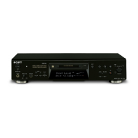
MAIN SECTION BLOCK DIAGRAM

PRINTED WIRING BOARDS

SCHEMATIC DIAGRAMS - BD SECTION

BD SECTION SCHEMATIC DIAGRAM (2/2)

MAIN SECTION PRINTED WIRING BOARDS

MAIN SECTION PRINTED WIRING BOARDS (SIDE B)

MAIN SECTION SCHEMATIC DIAGRAMS (1/3)

MAIN SECTION SCHEMATIC DIAGRAMS (2/3)

MAIN SECTION SCHEMATIC DIAGRAMS (3/3)

POWER SECTION PRINTED WIRING BOARDS

DISPLAY SECTION PRINTED WIRING BOARDS

DISPLAY SECTION SCHEMATIC DIAGRAMS

SECTION 7 EXPLODED VIEWS

FRONT PANEL SECTION EXPLODED VIEW

MECHANISM SECTION-1 EXPLODED VIEW

MECHANISM SECTION-2 EXPLODED VIEW

SECTION 8 ELECTRICAL PARTS LIST

ELECTRICAL PARTS LIST (BD BOARD)

Related product manuals