Do you have a question about the Sony MDS-JE780 and is the answer not in the manual?
Warning about invisible laser radiation when safeguards are defeated.
Identifies critical components for safe operation and replacement.
Explains causes and remedies for self-diagnosis error codes.
Steps to enter and use the self-diagnosis error history display mode.
Procedure for recording and displaying Iop data after optical pick-up replacement.
Checks to determine faulty locations before replacement.
Notes on replacing the BD board or MD mechanism deck.
Outlines the sequence for disassembling the unit and general steps.
General precautions before entering and using test modes.
Describes the methods to enter the test mode.
Guides checks before replacing parts and outlines the adjustment flowchart.
Covers key adjustments like Temp Comp, Laser Power, Traverse, Focus Bias, Auto Gain.
Covers Iop NV Save, Auto Check, and error display modes.
Checks temperature compensation offset.
Checks the laser power output.
Compares current Iop with reference Iop.
Steps for performing the Auto Check.
Procedure for checking traverse waveforms.
Procedure for setting initial adjustment values.
Procedure for adjusting temperature compensation offset.
Procedure for adjusting laser power output.
Saves Iop reference values to non-volatile memory.
Procedure for adjusting traverse mechanism settings.
Procedure for adjusting focus bias.
Procedure for checking focus bias.
Adjusts CD auto gain control output level.
Adjusts MO auto gain control output level.
Schematic diagram of the BD section (part 1).
Schematic diagram of the Main section (part 1).
Schematic diagram of the Main section (part 2).
Schematic diagram of the Display section.
Schematic diagram of the USB/Power section.
| Brand | Sony |
|---|---|
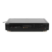
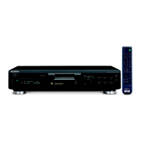
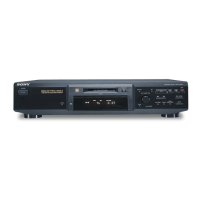
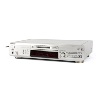
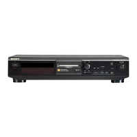
| Model | MDS-JE780 |
| Category | MiniDisc Player |
| Language | English |