Do you have a question about the Sony MDS-JE330 and is the answer not in the manual?
Guides the user on using the self-diagnosis function in error history display mode.
Critical notes for replacing chip components, including heat sensitivity.
Guidelines for repairing flexible circuit boards, focusing on soldering techniques.
Procedure for checking AC leakage from metal parts to earth ground.
Details the special jig for checking BD board waveforms and its terminal functions.
Verifies laser power output against specifications.
Assesses traverse waveform quality against specifications.
Evaluates focus bias by measuring C1 error rates.
Checks C PLAY error rate for MO discs.
Tests unit performance by checking error rates after self-operation.
Monitors internal temperature compensation offset.
Steps to perform a forced reset on the system microprocessor.
Interpreting displayed retry causes during recording operations.
Understanding track mode information displayed during playback.
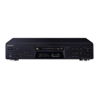
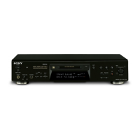
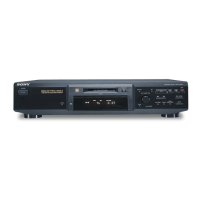
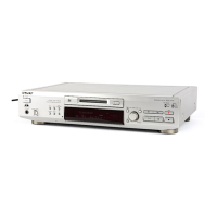
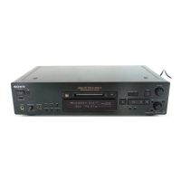
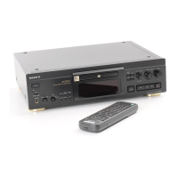
Diagram and identification of front panel controls and features.
Step-by-step guide to removing the unit's case and front panel.
Instructions for disassembling the slider (cam) mechanism.
Procedure for removing the base unit and BD board.
Guide to disassembling the SW board and loading motor.
Essential safety and operational precautions for test mode.
Methods for initiating the unit's test mode.
Correct procedure for safely exiting test mode.
How to navigate and operate functions within test mode.
Steps for operating the continuous playback mode.
Steps for operating the continuous recording mode for checks.
Overview of the EEP MODE for memory access; not for servicing.
Details the functions of various buttons within test mode.
Explanation of the various displays shown during test mode operation.
General guide for checking and adjusting components after replacement.
Safety guidelines for checking laser diode emission.
Handling precautions for the optical pick-up to prevent static damage.
Important precautions and the correct order for performing adjustments.
Method for creating a continuous recording disc for testing.
Checks temperature compensation offset at ambient 22-28°C.
Verifies laser power output using meter and voltmeter.
Analyzes traverse waveform using an oscilloscope.
Adjusts focus bias by measuring C1 error rates.
Verifies C1 error rate for MO discs, target below 80.
Verifies C1 error rate for CD discs, target below 50.
Tests unit functionality by checking error rates after self-operations.
Resets all adjustments to default values, excluding temp compensation.
Records and displays optical pick-up IOP values.
Adjusts temperature compensation offset at specific ambient temperatures.
Sets laser power output to 0.9mW and 7.0mW levels.
Adjusts traverse waveforms for read and write power.
Adjusts focus bias by identifying C1 error rate thresholds.
Checks CD error rate, ensuring it is below 20.
Checks MO error rate, requiring C1 below 50 and ADER at 00.
Verifies focus bias and tolerance by measuring C1 error.
Adjusts auto gain control output level for CD and MO discs.
Identifies specific points for adjustment and connection on the BD board.
Diagram illustrating the physical placement of all major circuit boards.
Shows the functional blocks and signal paths within the BD section.
Illustrates the functional blocks and signal paths within the main section.
Layout of components and traces on the BD section's printed wiring board.
Detailed schematic of the BD section, first of two parts.
Detailed schematic of the BD section, second of two parts.
Detailed schematic of the main section, first of two parts.
Detailed schematic of the main section, second of two parts.
Schematic diagram for the BD switch section.
Printed wiring board layout for the BD switch section.
Internal block diagrams for key integrated circuits.
Details the function of each pin for IC101 (CXA2523AR) on the BD board.
Exploded view showing parts for the case and back panel.
Exploded view detailing components of the front panel.
Exploded view of the MD mechanism (MDM-5A).
Exploded view of the base unit (MBU-5A).
List of electrical components for the BD board.
| Brand | Sony |
|---|---|
| Model | MDS-JE330 |
| Category | MiniDisc Player |
| Language | English |