Do you have a question about the Sony MDS-JE320 and is the answer not in the manual?
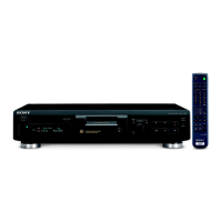
Overview of general technical specifications, power, dimensions, and accessories.
Details on audio and digital input types and their ratings.
Details on audio output types, ratings, and load impedance.
Warnings regarding battery handling, laser radiation, and component replacement.
Details on the special jig for checking BD board waveforms and its terminals.
Method to reset the system microprocessor when the unit is unresponsive.
Explains how to display and interpret retry causes during recording for fault finding.
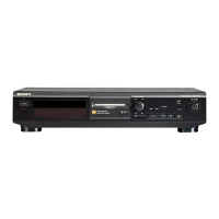
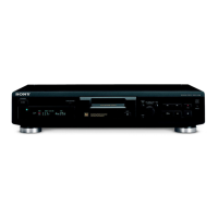
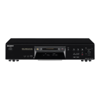
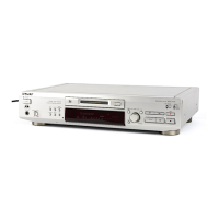
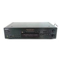
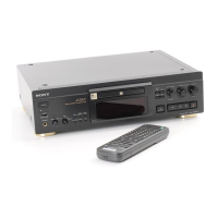
Identifies and illustrates the location of all external parts and controls on the unit.
Step-by-step guide for removing the case and front panel assembly.
Instructions for disassembling the upper, left, and right brackets.
Steps for removing the BD board and sub chassis.
Procedures for disassembling the shutter assembly and over write head.
Procedure for removing the slider assembly, including installation notes.
Guidelines for safe test mode usage, setting, exiting, and basic operations.
Explains button functions and interprets various test mode displays.
Safety guidelines for checking laser diode emission and handling the optical pick-up.
Steps for temperature compensation and laser power adjustments, including specified values.
Detailed steps for performing traverse adjustment using an oscilloscope and check disc.
Identifies connection points on the BD board for adjustments and waveform checks.
Diagram showing the physical layout and names of the main circuit boards.
Illustrates typical waveforms for various points in the BD and Main sections.
Block diagrams for key integrated circuits like CXA2523R.
Exploded diagram of the main unit sections, including boards and power components.
Exploded diagram showing the front panel components, buttons, and display window.
Exploded diagram of the first section of the MD mechanism deck.
Exploded diagram of the second section of the MD mechanism deck.
List of capacitors and connectors used in the BD board.
List of resistors, transistors, and other components for the main section.
| Brand | Sony |
|---|---|
| Model | MDS-JE320 |
| Category | MiniDisc Player |
| Language | English |