3. IC PIN FUNCTION DESCRIPTION
3-1. SERVO BOARD IC501 CXP84340-049Q (MD MECHANISM CONTROLLER)
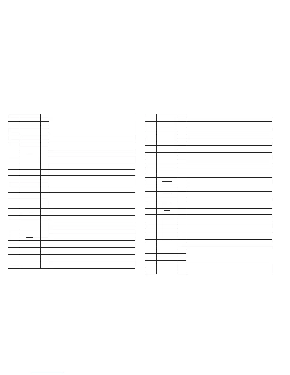
Pin No. Pin Name I/O Function
1 TIN3 I/O
2 TIN4 I/O Input of 4×8 matrix test keys
3 TIN5 I/O (“L” is always output, except in TEST mode)
4 TIN6 I/O (Not used in this set) (open)
5 TIN7 I/O
6 LOAD O Output of control for loading motor (M903) (Cartridge loading direction)
7 EJECT O Output of control for loading motor (M903) (Cartridge eject direction)
8 NCO O
Not used (open)
9 NCO O
10 MDMON O Mechanical deck power ON
11 E SW I Input of loading end switch (S902) “L”: Switch make
12 AGING O
Output of aging status in TEST mode “H”: Aging completed “L”: Under aging
(Not used in this set)
13 AGCHK O
Output of status when aging completed in TEST mode
“H”: Aging OK “L”: Aging NG (Not used in this set)
14 TFTON O
Output of free run status in TEST mode
“H”: Free run “L” : Normal (Not used in this set)
15 NCO O
16 NCO O Not used (open)
17 NCO O
18 DFCTSEL I
Select whether DEFECT2 function is used for CXD2650R (IC301)
“H”: Not used “L”: Used
19 DPLLSEL I
Select whether DPLL function is used for CXD2650R (IC301)
“H”: Not used “L”: Used
20 EMPHSEL I
Select whether Emphasis signal is output from pin or UNILINK
“H”: Output from pin “L”: Output from both pin and UNILINK
21 LOCK O Output of CLV LOCK status in TEST mode “H”: LOCK “L”: UNLOCK
22 NCO O Not used (open)
23 2M/4M I Select DRAM 2M or 4M “H”: 2M (internal DRAM) “L”: 4M (external DRAM)
24 TAEG E O Output of mechanism aging completion in TEST mode (Not used in this set) (open)
25 NCO O Not used (open)
26 MNT0 I Input of CXD2650R (IC301) monitor 0
27 MNT1 I Input of CXD2650R (IC301) monitor 1
28 MNT2 I Input of CXD2650R (IC301) monitor 2
29 MNT3 I Input of CXD2650R (IC301) monitor 3
30 RESET I Input of RESET signal
31 EXTAL I Input of SYSTEM CLOCK (10 MHz)
32 XTAL O Output of SYSTEM CLOCK (10 MHz)
33 VSS – Ground
34 TX O Output of CLOCK signal (32 kHz) for clock (Not used in this set) (open)
35 TEX I Input of CLOCK signal (32 kHz) for clock (Not used in this set) (Connected to the GND)
36 AVSS – Ground pin for A/D conversion input
37 AVREF – Input pin for A/D conversion input reference voltage
38 INIT I Initial input at the reset
Pin No. Pin Name I/O Function
39 TEMP I A/D input for temperature detection
40 ACNT I
A/D input to select the number of Load/Eject aging times
0H - 54H (30 times), 55H - OA9H (20 times), OAAH - OFFH (10 times)
41 DO SEL I A/D input to select digital output bits
42 EE CS O Output of EEPROM selection (Not used in this set) (open)
43 EE CKO O Serial clock output for EEPROM (Not used in this set) (open)
44 EE SIO I/O EEPROM data input/output (Not used in this set) (open)
45 MD SO O Data output to MD servo IC (SWDT of CXD2650R in this set)
46 LINKOFF O “LINKOFF” pin of SONY Bus “H”: LINKOFF “L”: LINK connected
47 UNIREQ O “REQUEST” pin of SONY Bus “H”: REQUEST ON (Not used in this set) (open)
48 UNICKI I “CLOCK IN” pin of SONY Bus
49 UNISI I “DATA IN” pin of SONY Bus
50 UNISO O “DATA OUT” pin of SONY Bus
51 MD CKO O “CLOCK OUT” pin to MD servo IC (CXD2650R in this set)
52 MD SI I “DATA IN” pin from MD servo IC (SRDT of CXD2650R in this set)
53 NCO O Not used (open)
54 SENS I “SENSE” input from MD servo IC (CXD2650R in this set)
55 CC XINT I Input of “XINT” interrupt signal from MD servo IC (CXD2650R in this set)
56 LIMIT IN I Input of sled most inside track detection switch
57 EJT KEY I Input of EJECT key “L”: EJECT button ON
58 ERROR PWM O Output of C1 ATER (Not used in this set) (open)
59 MD RST O
Output of RESET to MD servo IC (XRST of CXD2650R in this set)
/RF AMP IC (XRST of CXA2523R in this set)
60 BU IN I System power interruption check port
61 BUS ON I “BUS ON” input pin of SONY Bus
62 SQSY I Input of “SUBQ Sync” from MD servo IC (CXD2650R in this set)
63 C SW I
Input of cartridge loading switch (S901)
“H”: Cartridge eject completed “L”: Cartridge loading
64 MD LAT O Output of LATCH command to MD servo IC (XLAT of CXD2650R in this set)
65 MD ON O Power supply control to MD servo IC (CXD2650R in this set) “H”: Power on
66 DEEMP O Deemphasis control “H”: Deemphasis circuit ON
67 A MUTE O Output of audio mute “H”: Mute ON
68 NCO O Not used (open)
69 TSTCKO O Output of clock for TEST mode display (Not used in this set) (open)
70 TSTSO O Output of data for TEST mode display (Not used in this set) (open)
71 TSTMOD I Input of TEST mode “H”: Normal “L”: TEST mode
72 VDD – Power supply
73 NC – NC pin (Connected to VDD)
74 TOUT0 O
75 TOUT1 O
Output of 4×8 matrix test keys (Not used in this set) (open)
76 TOUT2 O
77 TOUT3 O
78 TIN0 I/O
Input of 4×8 matrix test keys
79 TIN1 I/O
(“L” is always output, except in TEST mode) (Not used in this set) (open)
80 TIN2 I/O
– 11 –
– 12 –


 To Next Page
 Loading...