– 14 –
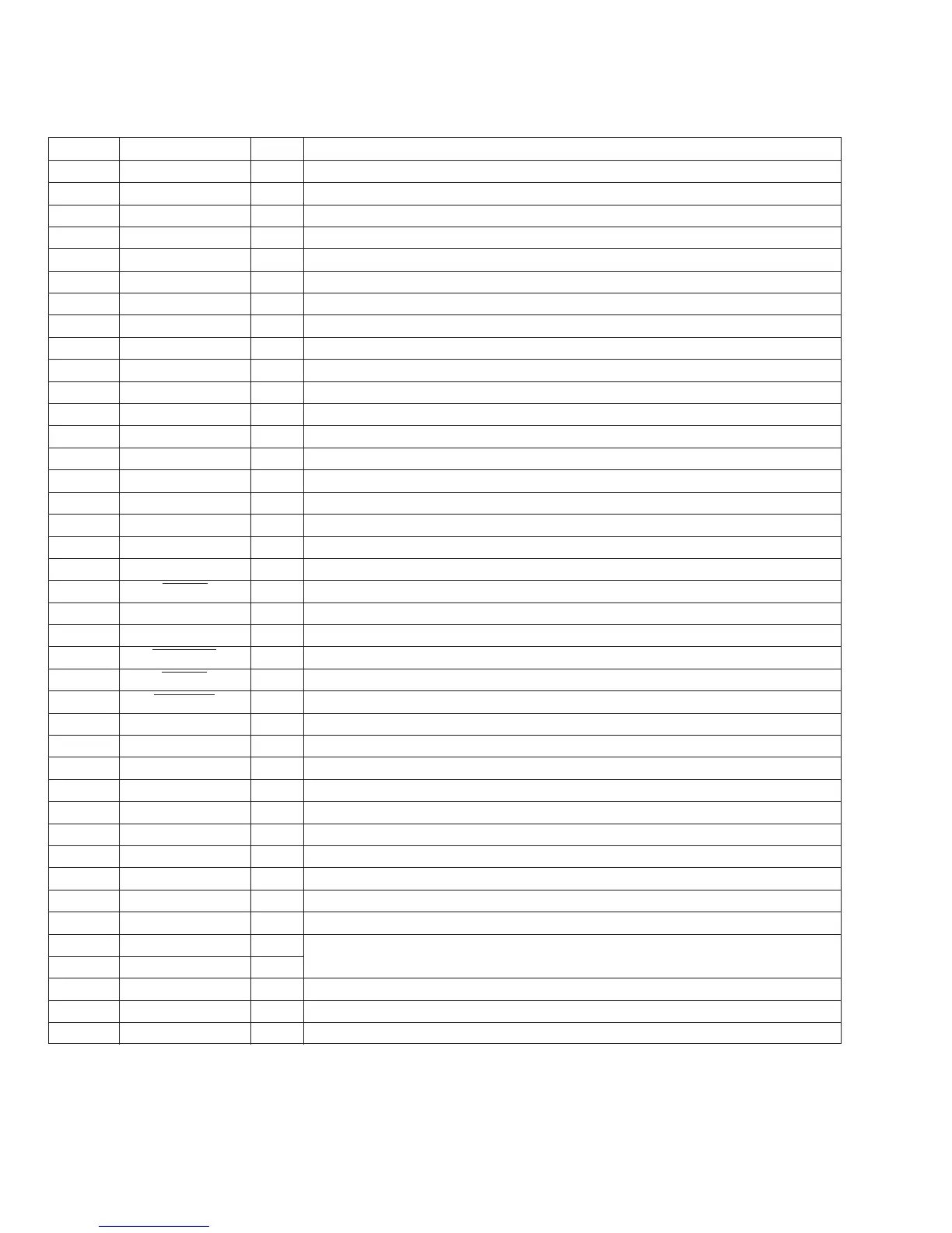
Pin No. Pin Name I/O Function
41 NCO O Not used (open)
42 PW SEL I Power select initial setting
43 RCIN1 I Input of rotary commander
44 TEST O Not used (open)
45 AMPMUTE O Power AMP mute control
46 BEEP O Output of buzzer control
47 MUTE O Output of system mute control
48 VOLCE O Output of electronic volume serial chip enable
49 VOLSO O Output of electronic volume serial data
50 VOLCKO O Output of electronic volume serial clock
51 PLLSI I Input of PLL serial data
52 PLLCKO O Output of PLL serial clock
53 PLLSO O Output of PLL serial data
54 PLLCE O Output of PLL serial chip enable
55 SD IN I Input of station detector detection “H”: SD detected
56 ST I/O In FM mode, stereo input, monaural output
57 DIMMER O Output of dimmer control
58 AD ON O Output of A/D converter ON control
59 RAMBU I Input of RAM reset detection
60 RESET I Input of RESET “L”: RESET
61 SIRCS I Input of remote controller
62 BUIN I Input of backup power detection
63 DOORSW I Not used (connected to the GND)
64 ACCIN I Input of accessory power detection
65 NOSESW I Input of front panel remove/attach detection.
66 TELMUTE I Input of telephone mute detection “H”: Mute ON
67 KEYACK I Key input acknowledge signal
68 VDD – Power supply
69 X OUT O Output of main ceramic oscillator (5 MHz)
70 X IN I Input of main ceramic oscillator (5 MHz)
71 GND – Ground
72 XT OUT O Output of sub crystal oscillator (32.768 kHz)
73 XT IN I Input of sub crystal oscillator (32.768 kHz)
74 AVDD – Power supply for A/D converter
75 AVREF – Reference voltage power supply for A/D converter
76 KEYIN0 I
Key input
77 KEYIN1 I
78 KEYSEL I Function select pin
79 VSM I A/D input of signal meter common to FM and AM
80 DSEL0 I A/D input of initial setting for the destination



 To Next Page