MEX-D30/V30
6
Precautions
Choose the installation location carefully so that the
unit will not interfere with normal driving operations.
Avoid installing the unit in areas subject to dust, dirt,
excessive vibration, or high temperature, such as in
direct sunlight or near heater ducts.
Use only the supplied mounting hardware for a safe and
secure installation.
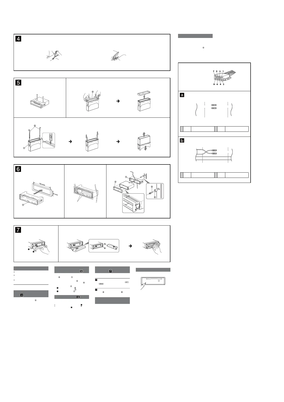
Mounting angle adjustment
Adjust the mounting angle to less than 30°.
Connecting the parking brake
lead
Be sure to connect the parking brake lead (light green) of
the power supply connection cable
to the parking
brake switch cord. e mounting position of the parking
brake switch cord depends on your car. Consult your car
dealer or your nearest Sony dealer for further details.
Removing the protection
collar and the bracket
Before installing the unit, remove the protection
collar
and the bracket from the unit.
1
Remove the pre-installed screws.
2
Remove the protection collar .
Pinch both edges of the protection collar and
push outwards, then pull out.
3
Remove the bracket .
Insert both release keys together between
the unit and the bracket
until they click.
Pull down the bracket , then pull up the unit
to separate.
Mounting example
Installation in the dashboard
Notes
Bend these claws outward for a tight t, if necessary ( -2).
Make sure that the 2 catches on the protection collar are properly
engaged in the slots of the unit (
-3).
How to detach and attach the
front panel
Before installing the unit, detach the front panel.
-A To detach
Before detaching the front panel, be sure to press .
Press
, then slide the front panel to the right side,
and pull out the le side.
-B To attach
Engage part of the front panel with part of the unit,
as illustrated, and push the le side into position until it
clicks.
Warning if your car’s ignition
has no ACC position
Unnecessary battery drainage will occur if the unit is
wired directly to a car ignition system that does not have
an ACC position. To avoid battery drainage, install a
suitable switch on the ACC line.
Reset button
When the installation and connections are completed, be
sure to press the reset button with a ballpoint pen, etc.
Foot brake type
Parking brake switch cord
Hand brake type
Parking brake switch cord
1 3
Dashboard
Fire wall
Claws
2
A
B
RedRed
Yellow Yellow
RedRed
Yellow Yellow
Power connection diagram
e auxiliary power connector may vary depending on
your car. Check your car’s auxiliary power connector
diagram to make sure the connections match correctly.
ere are two basic types (illustrated below). You may
need to switch the positions of the red and yellow leads of
the unit’s power supply connection cable
.
Aer matching the connections and switched power
supply leads correctly, connect the unit to the car’s power
supply. If you have any questions and problems
connecting your unit that are not covered in these
instructions, please consult your car dealer.
Auxiliary power connector
4 Yellow Continuous power supply 7 Red Switched power supply
4 Yellow Switched power supply 7 Red Continuous power supply
Face the hook inwards.
1
2
3