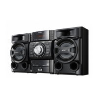
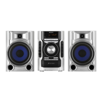
HCD-EC719iP/EC919iP
11
2-7. MAIN BOARD
2-6. MAIN BOARD BLOCK
5
Solder the short-land.
Note 2: When assembling the MAIN board block,
remove the solder of short-land after
connecting all flexible flat cable
and connector.
2 connector
(XP4)
6 flexible flat cable
(XP3)
7
MAIN board block
4
Lift the MAIN board block
in the direction of an arrow.
1
connector (XP5)
Note 3:
Since the wire is very thin, it is easy to cut.
When disconnecting, do it while holding the
connector part.
3 two claws
3 two claws
3 four claws
Note 1:
Before disconnecting the flexible flat cable of
the loader with FFC (TDL-5) (CDM1)
, solder the short-land.
7 MAIN board
2 connector
(XP2)
1 connector
(XP1)
– Rear right view –
3 screw
(silver 3 u 8)
3 screw
(silver 3 u 8)
3 two screws
(silver 3 u 8)
6 heatsink
5 three heat sink
screws
(3 u 8)
5 heat sink
screw
(3 u 8)
4 Remove the MAIN board block
in the direction of an arrow.
(EC919iP)

 Loading...