25
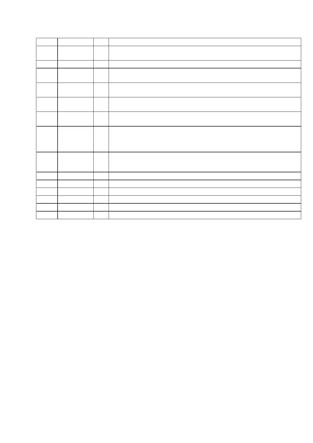
Pin No. Pin Name I/O
Description
87 LED 5.1CH O
LED drive signal output of the DVD 5.1CH indicator (D632) “H”: LED on
(Used for the STR-NX3 only)
88 LED GROOVE O
LED drive signal output of the GROOVE indicator (D631) “H”: LED on
89 BPF 1 I
Spectrum analyzer drive (low frequency) signal input from the spectrum analyzer band-pass filter
(IC401) (for 100 Hz)
90 BPF 2 I
Spectrum analyzer drive (low and middle frequency) signal input from the spectrum analyzer
band-pass filter (IC401) (for 400 Hz)
91 BPF 3 I
Spectrum analyzer drive (middle and high frequency) signal input from the spectrum analyzer
band-pass filter (IC401) (for 2 kHz)
92 BPF 4 I
Spectrum analyzer drive (high frequency) signal input from the spectrum analyzer band-pass filter
(IC401) (for 6 kHz)
93 KEY1 I
Key input terminal (A/D input)
S615 to S617, S619 to S624 (TUNER BAND, STEREO/MONO, TUNER MEMORY,
GROOVE, + M, – m, ENTER, DVD 5.1CH, PRO LOGIC) keys input
(S623 DVD 5.1CH, S624 PRO LOGIC keys: used for the STR-NX3 only)
94 KEY0 I
Key input terminal (A/D input)
S601 to S614 (I/1, DISPLAY, POWER SAVE/DEMO (STANDBY), VIDEO/DVD, MD, TAPE,
CD, TUNER, DSB, DBFB, PLAY MODE, REPEAT, EDIT, FILE SELECT) keys input
95 MODEL-IN I
Destination setting terminal
96 AVSS —
Ground terminal (for A/D conversion)
97 SPEC-IN I
Setting terminal for the version
98 VREF I
Reference voltage (+5V) input terminal (for A/D conversion)
99 AVCC —
Power supply terminal (+5V) (for A/D conversion)
100 POWER O
Power on/off control signal output terminal “L”: standby mode, “H”: power on
 Loading...