Do you have a question about the Sony PMC-107L and is the answer not in the manual?
Details about the CD player system, laser diode, speed, response, and wow/flutter.
Details about frequency range, IF, and aerial requirements for radio reception.
Details about recording system, response, and fast winding time for the cassette.
Details about speakers, outputs, power requirements, and power consumption.
Details on physical size, weight, and included items for the system.
Important warnings for safe operation, repair, and handling of components.
Step-by-step guide on how to insert and play a compact disc.
Instructions for tuning into radio stations and improving reception.
Guide on inserting and playing cassette tapes, including tape type.
Instructions for recording audio onto cassette tapes from various sources.
Steps and diagrams for removing the front cabinet.
Steps and diagrams for removing the CD chassis assembly.
Steps and diagrams for removing the power board.
Steps and diagrams for removing the main board.
Steps and diagrams for removing the CD board.
Steps and diagrams for removing the optical pick-up assembly.
Steps and diagrams for removing the mechanism deck block.
Steps and diagrams for removing the control board.
Procedures for measuring torque for various tape functions.
Procedures for measuring tape tension during playback.
Procedure for adjusting tape playback speed using a frequency counter.
Procedures for FM frequency coverage and tracking adjustments.
Procedures for MW/LW frequency coverage and tracking adjustments.
Important notes and procedures before performing CD section adjustments.
Steps for adjusting the optical pick-up traverse mechanism.
Procedure for adjusting the focus bias of the optical pick-up.
Reference for adjusting focus and tracking gain with performance notes.
Simplified procedures for focus and tracking gain adjustments.
Detailed pinouts for IC801, the system control/LCD drive IC.
Diagram illustrating the physical placement of all circuit boards within the unit.
Functional block diagram illustrating the CD signal path and components.
Functional block diagram of the main unit, covering tuner, tape, and power systems.
Detailed electronic schematic for the CD playback circuitry.
Electronic schematic for the front panel controls and display circuitry.
First part of the electronic schematic for the main unit.
Second part of the electronic schematic for the main unit.
Functional block diagrams for key integrated circuits used in the system.
Detailed internal functional blocks of the CXA1782BQ IC.
Internal functional diagrams for IC702, IC703, and IC704.
Diagram showing parts of the rear cabinet and their assembly.
Diagram showing parts of the front cabinet and their assembly.
Diagram showing parts of the upper cabinet and their assembly.
Diagram showing parts of the cassette mechanism, part 1.
Diagram showing parts of the cassette mechanism, part 2.
Diagram showing parts of the cassette mechanism, part 3.
Diagram showing parts of the cassette mechanism, part 4.
Diagram showing parts of the optical pick-up assembly and related components.
Diagram showing parts of the speaker assembly.
List of all capacitors used, including part numbers and specifications.
List of ICs, coils, transistors, resistors, and connectors for CD motor control.
List of diodes, ICs, coils, LCD, transistors, and resistors for the control section.
List of resistors, vibrator, connectors, jacks, coils, and switches for various sections.
List of switches, capacitors, connectors, trimmers, and diodes for key and main sections.
List of capacitors, filters, encapsulated components, connectors, trimmers, and diodes for the main section.
List of diodes, ICs, coils, transistors, and resistors for the main section.
List of resistors, transformers, vibrators, connectors, and capacitors for the main power section.
List of capacitors, connectors, diodes, fuses, resistors, transformers, and hardware.
| Brand | Sony |
|---|---|
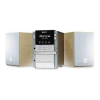
| Model | PMC-107L |
| Category | Stereo System |
| Language | English |