Do you have a question about the Sony PMC-DR45 and is the answer not in the manual?
Details of the CD playback mechanism, laser properties, wave length, and speed.
Specifications for the tape playback and recording functions, including frequency response.
General specs like speaker type, input/output jacks, and power output for non-US models.
Procedure for ensuring safety after repair, focusing on AC leakage testing methods.
Method for measuring AC leakage current from exposed metal parts to ground using specific testers.
Precautions for preventing electrostatic breakdown of the optical pick-up during repair.
Guidelines for safely checking laser diode emission from the optical pick-up objective lens.
Identifies critical safety components and stresses replacement with genuine Sony parts.
Instructions for inserting a CD and starting playback using the unit or remote control.
Steps for tuning FM/AM stations, auto-scanning, and improving broadcast reception.
Guide to inserting a tape and starting playback, including tape type recommendations.
Procedures for recording from CD or radio onto a cassette tape, including CD dubbing.
Instructions for setting the system's clock, including daylight saving time adjustment.
Procedure for removing the front cabinet assembly and associated screws.
Instructions for removing the front panel's circuit board and associated components.
Guide for disassembling the main control circuit board and connectors.
Procedure for removing the CD player's main circuit board, including solder removal.
Steps to disassemble the power supply circuit board and associated components.
Adjustments for tape speed, tension, and head azimuth alignment using test tapes.
Procedures for adjusting FM/AM frequency coverage, IF, and tracking using signal generators.
Focus bias check procedure for the CD player's optical block using an oscilloscope.
Detailed pin assignments and functions for key integrated circuits.
Diagrams showing the physical placement of various circuit boards within the main unit.
High-level functional overview of the tuner section's signal flow and components.
Layout of components and traces on the tuner section's printed circuit board.
Detailed circuit diagram for the power supply and distribution system, including protection circuits.
Exploded view showing the main chassis and external cabinet parts assembly.
Exploded view of the CD player mechanism assembly and its supporting chassis.
Exploded view of the left speaker unit and its internal components for assembly reference.
Exploded view of the right speaker unit and its internal components for assembly reference.
List of electrical components used on the CD board, including part numbers and descriptions.
List of electrical components used on the control boards, categorized by component type.
List of electrical components for the main unit and power supply boards.
List of electrical components specific to the tuner section, including coils and resistors.
| Brand | Sony |
|---|---|
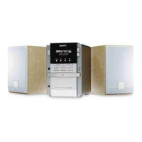
| Model | PMC-DR45 |
| Category | Stereo System |
| Language | English |