EasyManua.ls Logo

Sony PS-LX22 User Manual

Sony PS-LX22
34 pages
To Next Page IconTo Next Page
Page #1 background imageLoading...
Page #1 background image
StLX?-*r,$JLV€fi
TYF€
:,'"$EF,.{4,,
,d*t.
,,,'
K./Vlode/:,
."
$
Th*
FtLX?2lU$"
ean*dian
mod*f}'i* srot,*up"
plied
,with,
a
**rtridg*
ruhile,,th*
Pff,LX?2{AEp,
'
UK
:madall,;
Lp?
$).:
and LX2?8{A}
ars
cupplied'l
rlYirh
fin
xl--.r5s
cer{rid$*,:ard,the
F$.LX?SC,i* srip;
:
plied
with a VL-5 cartridge.
The
PS-LXZ2{A}
and
LXl2B{A},are
not *ppli*d'
with.a
dust
gsyer.
Turntable
Platter
Motor
Drive
system
SPECIFICATIONS
30.4 cm
(12
in.),
aluminum-alloy
diecast
Linear torque
BSL
(brushless
and slotless)
motor
Direct drive
Control system
FG
servo control
system
Speed
331/: rpm,45
rpm
Starting
characteristics
Comes to nominal
speed within a
half revolution
(33r/3
rpm)
Wow and f
lutter
0.04%
(WRMS)*
0.OSS%
(WRMS)
r0.0S%
(DtN)
Signal-to-noise
ratio
72
dB
(DlN-B)
Tonearm
Type
Statically
balanced
Pivot-to-stylus
length
216.5
mm
(g%
in.)
Overhang
16.5mm
(2thz
in.l
Stylus force
adjustment
range
0
-
3
g
Cartridge shell
weight
5.2
g
(US,
Canadian
model)
Cartridge weight
range
(including
a
cartridge
shell)
7.5-12s
-Continued
on
page
2-
Note
Appliance
conforms
with EEC
Directive 76/889 regarding
inter
|III11 ferencesuppression.
IITII
III
--
*
This new
measuring
method
concerns only
the turntable assembly, in-
lVtlqlOIllvtl
cluding
the
ptatter.
tt
6xctudes wow
and ftutter caused
by the tonearm, the
cartridge,
or
the
record.
Measured
by obtaining
signal from magnetic
pick-up
,,
",,,
Q
gg
6:$f6
s11, M
odgf,
f
$.L X:38{A}i
B LAgl( TYr.f
,::, :,,7${;p
Modgl,
,.,P$,LXZZG:
$l LVER,
TYFE
"Cana'di*in'M$del"',
ffi-LXza{Ah $,ILVE-H ?YPE
'A€F
Mod*f
P€;LX228:'BLACKTTYPE
AEF Mod*t
$TEfif'$. TlI HfiT
$ffi $Y$T[fTI,
SAFETY.RE
LATED
COMPONENT
WARN
ING
I I
COMPONENTS
IDENTIFIED
BY
SHADING
AND
MARK
I
oru rxe
scHEMATrc
DTAGRAMS
AND
tN
rHE
PARTS
LIST
ARE
CRITICAL
TO
SAFE
OPERATION.
REPLACE
THESE
COMPONENTS
WITH
SONY
PARTS
WHOSE
PART
NUMBERS
APPEAR
AS
SHOWN
IN
THIS
MANUAL
OR IN
SUPPLEMENTS
PUBLISHED
BY
SONY.
ATTENTION
AU
COMPOSANT
AYANT RAPPOBT
A
la
sEcunlr€r
LEs
coMposANTs
tDENTrnEs
paR
uNE TRAME ET
UNE
MARoue
I
sun LEs
DrAGRAnarues
scnE-
MATrouEs,
LEs vuEs
expuosEes
ET
LA LtsrE
oes
pleces
soNT
cRtrlouEs
pouR
la
sEcunrrd
DE FONCTIONNEMENT.
NE REMPLACER
CES
coMposANTs
ouE
pAB
oes
prices
soNy
DoNT
les ruumEnos
soNT oonrvEs
DANS
cE MANUEL
ou DANS
ues
supplemsNrs
pueLtEs
pAR
soNy.
SONY
SER1JICE MANUAL
www.hifiengine.com
Question and Answer IconNeed help?

Do you have a question about the Sony PS-LX22 and is the answer not in the manual?

Sony PS-LX22 Specifications

General IconGeneral
TypeBelt Drive
Drive SystemBelt Drive
MotorDC Motor
Overhang15 mm
Output Voltage2.5 mV
Frequency Response20 Hz - 20 kHz
Recommended Load Impedance47 kΩ
Signal-to-Noise Ratio70 dB
Power RequirementsAC 120V, 60Hz
Speed33, 45 rpm
PlatterAluminum
Tonearm TypeStatic Balance
Cartridge TypeMoving Magnet (MM)

Summary

Product Specifications

Turntable and Tonearm Details

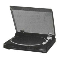
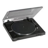
Covers platter, motor, drive system, and tonearm characteristics.

General Safety Component Warning

Highlights critical safety components and provides warnings in multiple languages.

Model Identification and Features

Cartridge Compatibility and Specifications

Details for XL-150 and VL-5 cartridges, including frequency response and load impedance.

General Unit Specifications

Covers power requirements, consumption, dimensions, and net weight.

Key Product Features

Highlights features like BSL motor, low-mass tonearm, and precise tracking force setting.

Service and Safety Procedures

Safety Check-Out and Leakage Test

Procedures for safety verification and AC leakage measurement methods.

System Block Diagram

Overview of the unit's functional blocks and signal flow.

Circuit Description and Motor Operation

BSL DC Servo Motor Description

Explanation of the BSL DC servo motor's circuit and internal workings.

Motor Component Views

Diagrams illustrating the motor's internal and external components.

FG Board Signal Generation

Electromotance and Frequency Calculation

Explanation of electromotance generation and frequency calculation based on rotor rotation.

Disassembly Guide

Turntable and Bottom Board Removal

Steps for disassembling the turntable assembly and the main unit's bottom board.

Component Removal Instructions

Servo Amp, Stator, Rotor, and FG Board Removal

Detailed steps for removing key internal assemblies like the servo amp and motor.

Internal Wiring and Board Assembly

Wire Routing and Servo Board Connection

Guidance on routing motor coil wires and connecting the servo amp board.

Mechanical Assembly Adjustments

Anti-Skating Knob and Lifter Lever Installation

Procedures for installing the anti-skating knob and the lifter lever assembly.

Main Lever Installation

Drive Gear and Main Lever Assembly

Steps for installing the main lever mechanism and its related parts.

Tonearm Assembly Details

Step-by-Step Tonearm Construction

Instructions for assembling the tonearm from its various parts.

Tonearm Installation and Setup

Mounting and Switch Lever Positioning

Procedures for installing the tonearm and correctly setting the switch lever.

Lubrication Guide

Lubrication Points for Key Components

Specifies lubrication for the motor rotor shaft, lifter lever, and push rod.

Mechanical Adjustment Procedures

Tonearm Sensitivity and Auto-Return Adjustment

Adjustments for tonearm balance sensitivity and automatic return position.

Tonearm Height Adjustment

Adjusting Tonearm Lifter Height (A & B)

Detailed steps for setting the tonearm lift height using specific adjustment screws.

Cartridge Leveling Procedure

Horizontal Cartridge Alignment

Steps to ensure the cartridge is level by adjusting the locking collar.

Electrical Adjustment: Speed

Speed Accuracy Calibration

Instructions for adjusting playback speeds using a frequency counter and potentiometers.

Electrical Adjustment: Gain & Offset

Gain and Offset Calibration Steps

Procedures for setting gain and offset levels using an oscilloscope.

Diagrams and Layouts

PS-LX22 Former Type Mounting Diagram

Visual guide for component placement on the former type PS-LX22.

Wiring Diagrams and Board Layouts

Motor, FG, and Power Input Board Wiring

Wiring schematics for the BSL motor, FG board, and power input board.

Schematic Diagrams: Core Circuits

Servo, Switch, and Phono Board Schematics

Detailed circuit diagrams for the servo amp, switch board, and phono board.

Schematic Diagrams: Drive and Power

Motor Drive and Power Input Circuit Schematics

Circuit diagrams for the motor drive section and the power supply.

Mounting Diagrams: PS-LX22 New Type

Component Layout for New Type Models

Visual guide for component placement on the new type PS-LX22/B/C/(A)/B(A).

Wiring Diagrams: New Type

Motor, FG, and Power Input Board Wiring (New Type)

Wiring details for the BSL motor, FG board, and power input board on new type models.

Schematics: Servo and Switch Boards (New Type)

Detailed Circuits for New Type Boards

Circuit diagrams for the servo and switch boards of newer model versions.

Schematics: Drive and Power (New Type)

Circuit Details for New Type Drive and Power

Circuitry for the motor drive and power input sections on new type models.

Exploded Views: Main Unit

Turntable and Chassis Component Breakdown

Visual guide to the main unit's parts and their assembly.

Exploded Views: Tonearm Assembly

Tonearm Mechanism Parts Breakdown

Visual guide to the tonearm's components and assembly.

Exploded Views: Tonearm Details

Tonearm Mechanism and Accessories Breakdown

Detailed visual breakdown of tonearm parts and related accessories.

Parts Lists and Notes

General and Accessory Parts Identification

Listing of common parts and accessory items with their part numbers.

Component Identification and Notes

Accessory Parts and Packing Material List

Details on accessories, packing materials, and important notes for service.

Electrical Parts Listing

Identification of Electrical Components

List of electrical components like diodes, ICs, transistors, and potentiometers.

Capacitor Specifications and Part Numbers

Mylar and Tantalum Capacitor Ratings

Tables detailing mylar and tantalum capacitor types, values, and part numbers.

Resistor and Hardware Nomenclature

Carbon Resistor Values and Hardware Definitions

Lists of 1/4 watt carbon resistors and definitions of hardware terms.

Related product manuals