*
The
above adjustment may affect the landing, so after adjust-
ment, check the landing again.
7.
Paint-lock the knobs after adjustment.
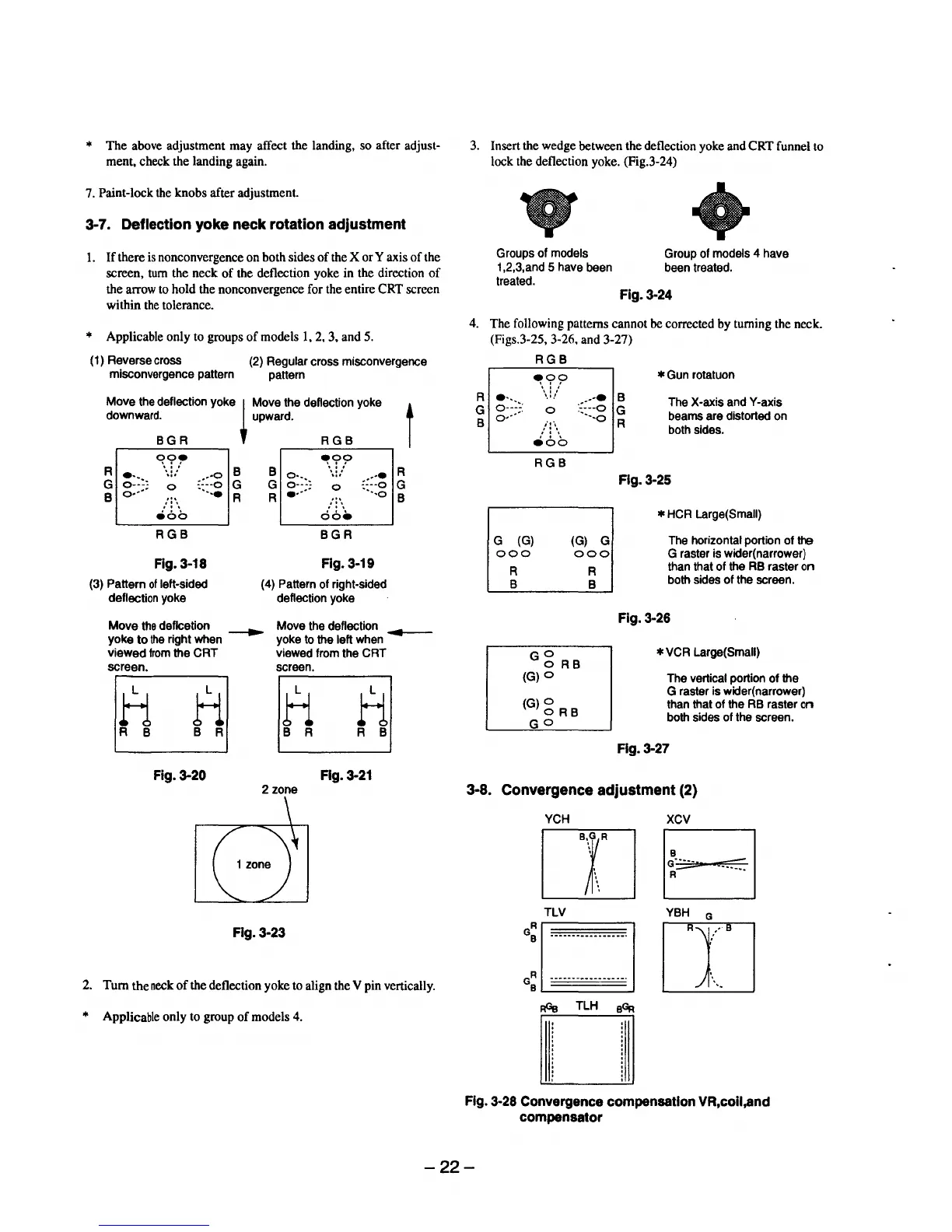
3-7. Deflection yoke neck rotation adjustment
1.
If
there
is
nonconvergence on both sides
of
the X or Y axis
of
the
screen,
turn
the neck
of
the deflection yoke in the direction
of
the arrow to hold the nonconvergence for the entire CRT screen
within
the
tolerance.
* Applicable only to groups
of
models
1,
2,
3, and 5.
( 1) Reverse cross
misconvergence pattern
(2) Regular cross misconvergence
pattern
Move
the
deflection yoke
~
Move the deflection yoke t
downward. upward.
BGR
RGB
R
~:::,
~.:r.r
::::~
G
0
B
o-···
...
,':\
eo
a
RGB
Fig. 3-18
(3) Pattern
of
left-sided
deflection yoke
B
G
R
B
~)
~,:f.,?
---··
G
0
~:::g
R
.
..
...
.
'.
doe
BGR
Fig. 3-19
(4) Pattern of right-sided
deflection yoke
R
G
B
Move
the deflcetion
__..
Move the deflection
.......
e--
yoke
to
the
right when yoke to the left
when
viewed
from
the CRT viewed from the CRT
screen. screen.
H
H H
H
R B
B R
B R R B
Fig. 3-20 Fig.
3-21
3. Insert the wedge between the deflection yoke and CRT funnel to
lock the deflection yoke. (Fig.3-24)
•
Groups of models Group of models 4 have
1 ,2,3,and 5 have been been treated.
treated.
Fig.3-24
4. The following patterns cannot be corrected by turning the neck.
(Figs.3-25, 3-26, and 3-27)
RGB
*
Gun
rotatuon
R
•·-.
G
g::)
B
~,f.?
'.•.'
0
--·•
B
::
...
o G
··--o
R
The X-axis andY-axis
beams are distorted on
both sides.
it\
,' : \
e6o
RGB
G (G)
(G)
G
000
000
R
B
Gg
RB
(G)O
(G)g
RB
GO
R
B
Fig.
3-25
*
HCR
Large( Small)
The
horizontal portion of ttB
G raster is wider(narrower)
than that of the
RB
raster on
both sides of the screen.
Fig.
3-26
*VCR
Large(Small)
The vertical portion of the
G raster is wider( narrower)
than that of the
RB
raster on
both sides of the screen.
Fig.
3-27
2 zone 3-8. Convergence adjustment (2)
Fig.3-23
2.
Tum
the
neck
of
the deflection yoke to align the V pin vertically.
* Applicable only to group
of
models 4.
YCH
XCV
ITJB
TLV
YBH
G
G=o-----------------
ITJJ/
GR
•••••••••••••••••·
\
8
~
AGe
TLH
9~
Fig.
3-28
Convergence compensation VR,coil,and
compensator
-22-
 Loading...