Note : When adjustment is insufficient, use pennalloy for perfect
adjustment.
1.
Group
of
models 4 (See Table 3-3.)
l. Input a cross-hatch signal.
2.
Make adjustment with the
TLV,
YCH, YBH VR, and XCV coils
of
the deflection yoke to minimize nonconvergence.
3.
When the nonconvergence
of
the TILT component is included in
the horizontal convergence, make adjustment with the TLH
com-
pensator. (Fig.3-28)
2.
Groups of models 1, 2, and 3 (See Table 3-3.)
I. Input a cross-hatch signal.
2.
Make adjustment with the
TLV,
YCH VR, and XCV coils
of
the
deflection
yoke to minimize nonconvergence.
3.
When the nonconvergence
of
the TILT component is included
inthe horizontal convergence, insert the TLH compensator into
the deflection yoke for adjustment. (Fig.3-28)
3.
Group of models 5
(See
Table 3-3.)
I. Input a cross-hatch signal.
2.
Make adjustment with the XCV coil
of
the deflection yoke to
minimize nonconvergence.
3.
When the nonconvergence
ofthe
TILT component is included in
the vertical convergence, insert the TLV compensator into the
deflection yoke for adjustment. (Fig.3-28)
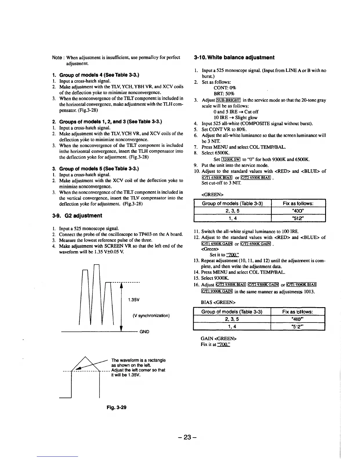
3·9. G2 adjustment
l. Input a 525 monoscope signal.
2.
Connect the probe
of
the oscilloscope to TP403 on the A board.
3.
Measure the lowest reference pulse
of
the three.
4.
Make adjustment with SCREEN
VR
so
that the left end
of
the
wavefonn will
be
1.35 V±0.05
V.
1.35V
(V synchronization)
----------------~----GND
The waveform is a rectangle
as shown
on
the left.
____
Adjust the left corner
so
that
it
will be 1.35V.
Fig. 3·29
3·10.
White balance adjustment
1.
Input a 525 monoscope signal. (Input from LINE A
or
B with no
burst.)
2.
Set as follows:
CONT:O%
BRT: 50%
3.
Adjust
!SUB-BRIGHT!
in the service mode so that the 20-tone gray
scale will be as follows:
0 and 5 IRE
-+
Cut
off
10 IRE
-+
Slight glow
4. Input 525 all-white
(COMPOSITE signal without burst).
5.
Set
CONT
VR
to 80%.
6. Adjust the all-white luminance so that the screen luminance will
be
3 NIT.
7. Press MENU and select
COL
TEMP/BAL.
8.
Select 6500K.
Set
"'l3""2oo=K""'sw""l
to ''0" for both 9300K and 6500K.
9. Put the unit into the service mode.
10. Adjust to
the
standard values with
<RED>
and
<BLUE>
of
lcrn
6500K
BIASI
or
lcm
6500K
BIASI
.
Set cut-off to 3
NIT.
<GREEN>
Group of models (Table 3-3) Fix
as
follows:
2,3,5
"400"
1,
4
"512"
11. Switch the all-white signal luminance to 100 IRE.
12. Adjust to the standard values with <RED>
and
<BLUE>
of
lcrn
6500K
GAINI
or
!ern
6500K
GAiNJ
.
<Green>
Set
it
to
:ZOO.:
13. Repeat adjustment (10, 11, and 12) until the adjustment is com-
plete, and then write the adjustment data.
14. Press
MENU
and select
COL
TEMP/BAL.
15.
Select 9300K.
16. AdjustiCit2
r.:=_""'9300=K~BI,.A"'sllcm
9300K
GAiNI
or
lcrrt
9300K
BIASI
lcm
9300K
GAIN!
in the same manner as
adjustme~ts
1013.
BIAS
<GREEN>
Group of models (Table 3-3)
2,
3,
5
1, 4
GAIN
<GREEN>
Fix it at
:ZOO.:
Fix
as
follows:
"4()0"
"512~'
-23-
 Loading...