<0
I
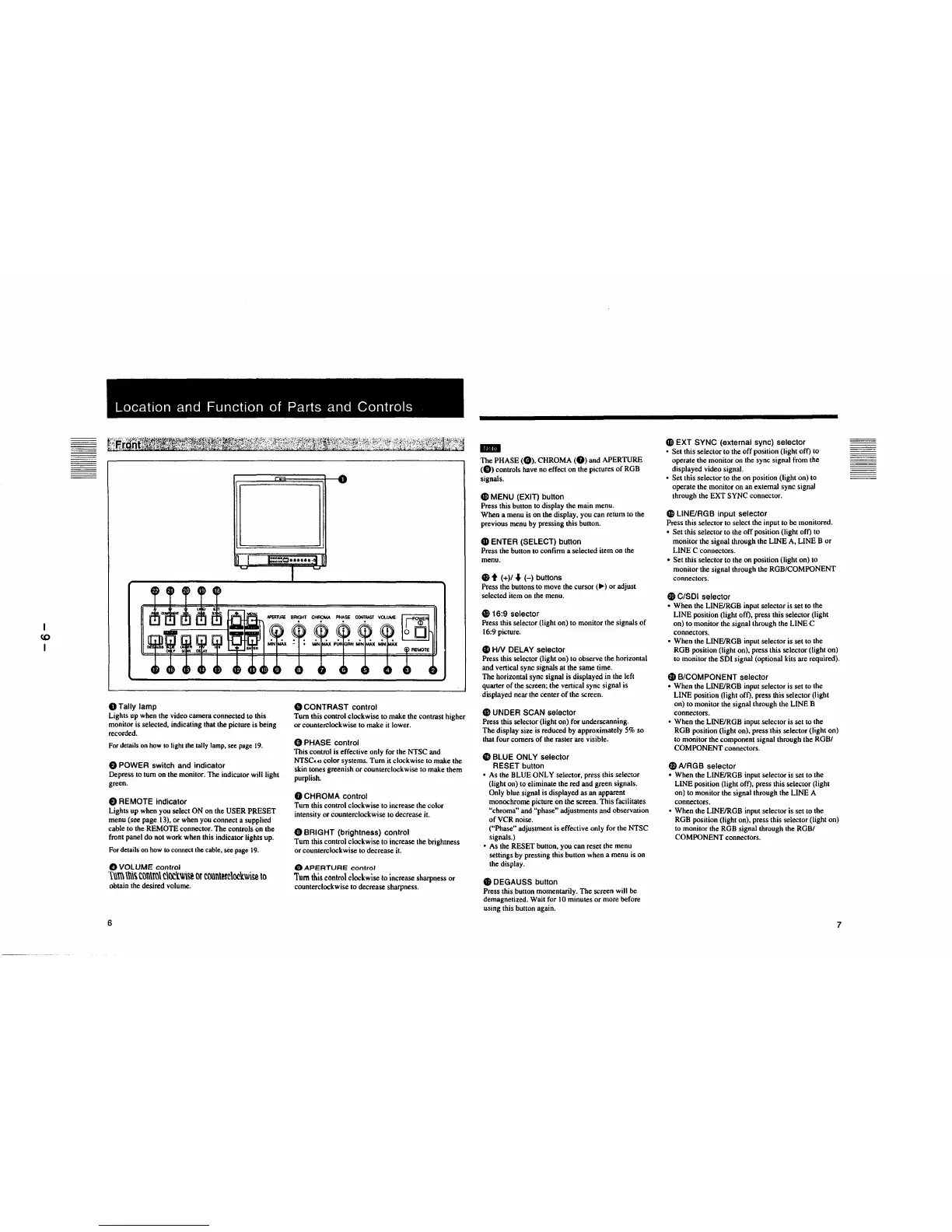
Location
and
Function
of Parts and
Controls
OTally
lamp
Lights
up
when the video camera connected to this
monitor is selected, indicating that the picture is being
recorded.
For details
on
how
to light
the
tally lamp, see page
19.
8 POWER switch and indicator
Depress to tum
on
the monitor. The indicator will light
green.
8 REMOTE indicator
Lights
up
when you select
ON
on the
USER
PRESET
menu (see page 13),
or
when you connect a supplied
cable to the REMOTE connector.
The
controls on the
front panel
do
not work when this indicator lights up.
For details on
how
to
connect the cable, see page 19.
0
VOLUME
control
1\\m
\\\\~
t()l\\m\
c\oc'lwi~
or
counterclockwise
to
obtain the desired volume.
6
8 CONTRAST control
Tum
this control clockwise
to
make the contrast higher
or
counterclockwise to make it lower.
0 PHASE control
This
control is effective only for the NTSC and
NTSC
•.
o color systems.
Tum
it clockwise
to
make the
skin tones greenish or counterclockwise to make them
purplish.
0 CHROMA control
Tum
this control clockwise
to
increase the color
intensity or counterclockwise to decrease it.
8 BRIGHT (brightness) control
Tum
this control clockwise to increase the brightness
or
counterclockwise to decrease it.
G)
APERTURE
control
Tum
this control clockwise to increase sharpness
or
counterclockwise
to
decrease sharpness.
IIIII
The
PHASE
(0).
CHROMA
(f))
and
APERTURE
(Ci))
controls have no effect on the pictures
of
RGB
signals.
G)
MENU (EXIT) button
Press this button to display the main menu.
When a menu
is
on the display, you can return to the
previous menu by pressing this button.
G)
ENTER (SELECT) button
Press the button to confirm a selected item on the
menu.
48
t (+)/
..
(-)
buttons
Press the buttons to move the
cursor(.,.)
or
adjust
selected item on the menu.
C816:9 selector
Press this selector (light on)
to
monitor the signals
of
16:9 picture.
4D
HN
DELAY selector
Press this selector (light on)
to
observe the horizontal
and vertical sync signals at the same time.
The
horizontal sync signal is displayed in the left
quarter
of
the screen; the vertical sync signal is
displayed near the center
of
the screen.
49
UNDER SCAN selector
Press this selector (light on) for underscanning.
The
display size is reduced by approximately 5% so
that four comers
of
the raster are visible.
4D
BLUE ONLY selector
RESET button
• As the
BLUE
ONLY selector, press this selector
(light on) to eliminate the red and green signals.
Only blue signal is displayed as an apparent
monochrome picture on the screen.
This
facilitates
"chroma" and "phase" adjustments and observation
of
VCR noise.
("Phase" adjustment is effective only for the NTSC
signals.)
• As the RESET button, you can reset the menu
settings by pressing this button when a menu is on
the display.
G)
DEGAUSS button
Press this button momentarily.
The
screen will be
demagnetized. Wait for I
0 minutes or more before
using this button again.
CD
EXT SYNC (external sync) selector
• Set this selector to the
off
position (light off) to
operate the monitor on the sync signal from the
displayed video signal.
•
Set
this selector
to
the on position (light on) to
operate the monitor on an external sync signal
through the
EXT
SYNC connector.
G>
LINEIRGB input selector
Press this selector to select the input
to
be monitored.
•
Set
this selector
to
the
off
position (light off)
to
monitor the signal through the LINE A, LINE B
or
LINE
C connectors.
•
Set
this selector
to
the on position (light on) to
monitor the signal through the
ROB/COMPONENT
connectors.
G)
C/SDI selector
• When the LINE/ROB input selector is set to the
LINE
position (light off), press this selector (light
on)
to
monitor the signal through the
LINE
C
connectors.
• When the LINE/ROB input selector is set to the
RGB position (light on), press this selector (light on)
to monitor the
SOl
signal (optional kits are required).
Gl
B/COMPONENT selector
• When the LINE/ROB input selector is set to the
LINE
position (light off), press this selector (light
on)
to
monitor the signal through the LINE B
connectors.
• When the LINEIRGB input selector is set
to
the
ROB position (light on). press this selector (light on)
to monitor the component signal through the
ROB/
COMPONENT
connectors.
$ A/RGB selector
• When the LINEIRGB input selector is set to the
LINE position (light off), press this selector (light
on)
to
monitor the signal through the LINE A
connectors.
•
When
the LINEIRGB input selector is set to the
RGB position (light on), press this selector (light on)
to monitor the
ROB signal through the ROB/
COMPONENT
connectors.
7
 Loading...