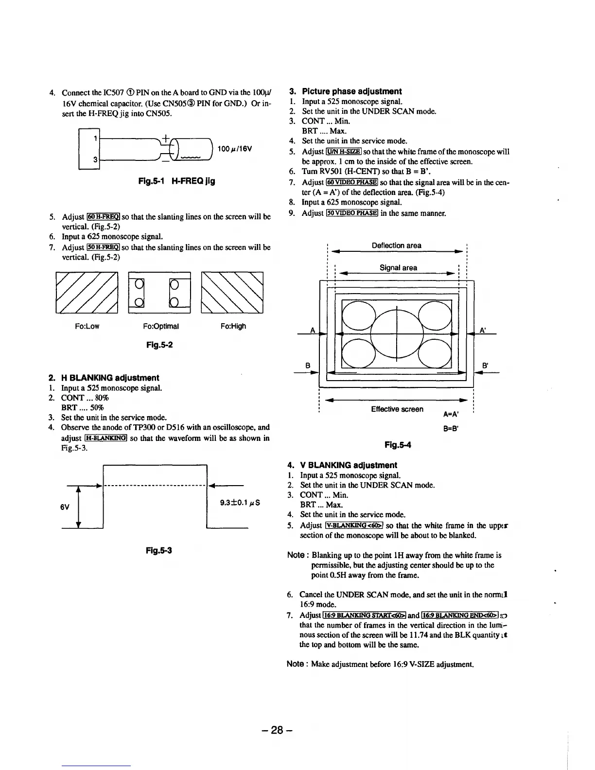
4.
Connect
the IC507
<D
PIN on the A board to
GND
via the
1001Jf
16V chemical capacitor. (Use
CN505@
PIN
for GND.)
Or
in-
sert the H-FREQ
jig
into CN505.
100p/16V
Rg.S-1 H-FREQ jig
5. Adjust
160
H-FREQI
so that the slanting lines on the screen will be
vertical. (Fig.5-2)
6. Input a 625 monoscope signal.
7. Adjust
ISO
H-FREQI
so that the slanting lines on the screen will be
vertical. (Fig.5-2)
Fo:Low Fo:Optimal Fo:High
Fig.5-2
2.
H BLANKING adjustment
1.
Input a 525 monoscope signal.
2.
CONT
...
80%
BRT
....
50%
3. Set the unit in the service mode.
4. Observe
the
anode
of
TP300
or
D516 with an oscilloscope, and
adjust
IH-BLANKINGI
so
that the waveform will be as shown in
Fig.5-3.
-.--_...
..
1----
------------------------
-+----
6V
9.3±0.1
pS
Fig. 5-3
3.
Picture phase adjustment
1.
Input a 525 monoscope signal.
2.
Set
the unit in the UNDER
SCAN
mode.
3.
CONT
... Min.
BRT ....
Max.
4. Set the unit in the service mode.
5. Adjust
IUIN
H-SJZBI
so that the white frame
of
the monoscope will
be approx. 1 em to the inside
of
the effective screen.
6.
Tum
RV50l (H-CENT) so that B =
B'.
7. Adjust
160
VIDEO
PHASE
I so that the signal area will be in the cen-
ter
(A=
A')
of
the deflection area. (Fig.5-4)
8. Input a 625 monoscope signal.
9. Adjust
lsoVIDEOPHASEI in the same manner.
Deflection area
Signal area
' '
Effective screen
Fig.5-4
4.
V BLANKING adjustment
l.
Input a 525 monoscope signal.
2.
Set the unit in the UNDER
SCAN
mode.
3.
CONT
... Min.
BRT
... Max.
4.
Set the unit in the service mode.
' '
A=
A'
B=B'
A'
B'
---
5. Adjust IV-BLANKING<60>1
so
that the white frame in the upper
section
of
the monoscope will be about to be blanked.
Note:
Blanking up to the point 1H away from the white frame is
permissible, but the adjusting center should be up to the
point
0.5H away from the frame.
6. Cancel the UNDER SCAN mode, and set the unit in the normal
16:9 mode.
7. Adjust
lr.-t6;;:;:9"'B'"LANKIN,.....=:uo"'s""-r.":AKr=-<60>::;;;:-,l
and lt6:9 BLANKING
BND<60>
ilo
that the number
of
frames in the vertical direction in the lumi-
nous section
of
the screen will
be
11.74 and the BLK quantity
at
the top and bottom will be the same.
Note
: Make adjustment before 16:9 V-SIZE adjustment.
-28-
 Loading...