:::
:::
(!)
'"'
-----,
~LY
-,
ON
I
_____
J
CN303
-MICRO
WHT
12P
j
J 0
'-
u
>-
..,,_
~
>
;
~
z
&,
z,
"'
..
"'
'
'
'
...
"'"'
...
.,
"'~
l!G!TAL
OPTION
·MOTE
OPTION
~
r;;
r:;
"'
'
"'
...
•• 0
)
~
~
0:
'-'-
l308
WHT-L
4P
- N
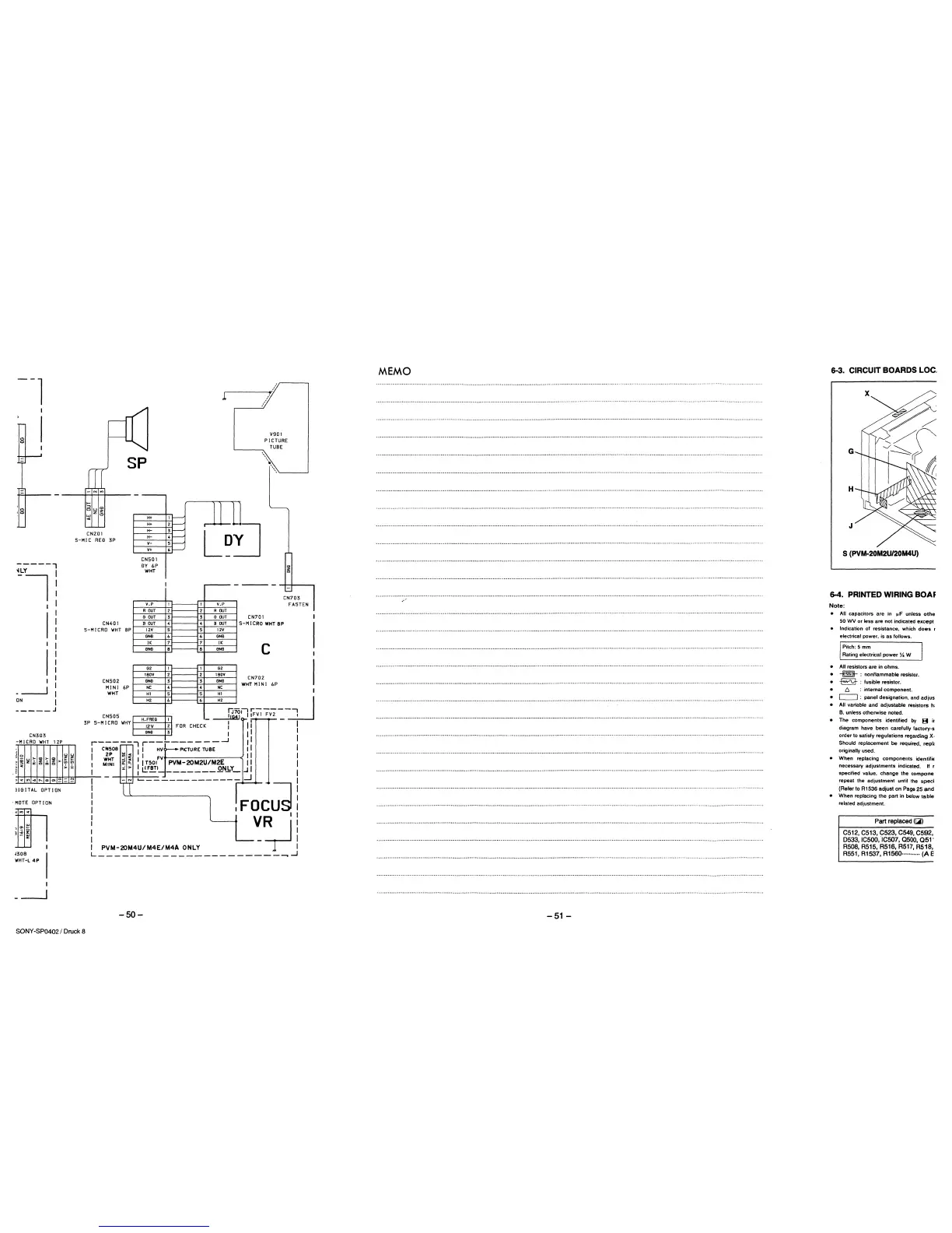
SP
CN201
5-MIC
REfl
3P
CN401
5-MICRO
WHT
BP
CN502
MINI
6P
WHT
CNSOS
3P
S-MICRO
WHY
I
I
H+
H+
H-
H-
v-
V+
CNSOI
flY
6P
WHT
V.P
R
OUT
GOUT
BOUT
12V
GNll
JK
ClN!l
G2
lBOV
GNll
NC
Hl
HZ
H.FREQ
12V
GN!l
I
1
2
3
4
5
6
7
8
1
2
3
4
5
6
1
zl
FOR
31
l
1
V.P
2
R
OUT
3
GOUT
4
BOUT
5
12V
6
GNll
7
IK
8
GNll
1 G2
2
1
BOY
3
GNll
4
NC
5
H1
6
HZ
-
CHECK
-
CN701
V901
PICTURE
TUBE
\.
\\._
__
__j
CN703
FASTEN
5-M
I
CRO
WHT
BP
c
CN702
WHT
MIN
I
6P
oiJ
it=~-;;;--=_~
IJ7
1!G41
I
I
11
I
I
1
1
I
r------,
r--~------_...J
II
I
CN508
I I
HV
PICTURE
TUBE
II
I
I
:~T
~~
1
1
FV
II
MINI
~
~
I I
T501
PVM-20M2U/M2E
II
i > I
L!!BTl
_______
.Q.fotbY_
..J
I
--1-t--!--.;.L-------
--
-------
_j
I
I
I
I
FOC~
VR
I
I
;_J
I -
I
PVM-20M4U/M4E/M4A
ONLY
L----------------------~~
-50-
SONY -SP0402 I Druck 8
MEMO
-51-
6-3. CIRCUIT
BOARDS
LOC.
G
H
J
S (PVM-20M2U/20M4U)
6-4. PRINTED WIRING BOAF
Note:
• All capacitors
are
in
1-1F
unless
othe
50 WV
or
less are
not
indicated
except
• Indication of resistance. which
does
r
electrical power. is as follows.
Pitch: 5 mm
Rating electrical
power
Y.
W
• All resistors
are
in ohms.
• -m- : nonflammable resistor.
•
-E2'9-
: fusible resistor.
• 6 : internal component.
•
c=J
: panel designation. and
ad
jus
• All variable and adjustable resistors
h;
B.
unless otherwise noted.
• The components identified
by
B
ir
diagram have
been
carefully factory-s
order to satisfy regulations regarding
X·
Should
replacement be required.
repll
originally used.
• When replacing components identifiE
necessary adjustments indicated.
If r
specified value. change the compone
repeat the adjustment until the
speci
(Refer to R1536 adjust on Page 25
and
• When replacing the part in below
table
related adjustment.
Part replaced ([;il)
C512, C513, C523, C549, C592,
0533, IC500, IC507, 0500,
051"
R508, R515, R516, R517, R518,
R551, R1537,
R1560··········· (A E
 Loading...