Overview
Location and Function of Parts
GB
8
R SHIFT button and indicators
When pressing the SHIFT button, the lower
indicator lights and the GROUP/POSITION
buttons can be used for group/position numbers 9 to
16. If you release the SHIFT button, the upper
indicator will light and the GROUP/POSITION
buttons can be used for group/position numbers 1 to
8.
S SELECT button
The camera group number can be changed by
pressing the GROUP/POSITION button while this
button is pressed. To select camera group numbers
9 to 16, press and hold the SHIFT button (the lower
indicator lights).
The SELECT button works only for the LAN
connection.
T POWER button
Press this button to light the CAMERA button(s)
corresponding to the status of the connected
camera(s).
Ye ll ow : The power of the camera is on.
Green: The camera is in standby mode.
Off: No camera is connected.
Hold down this button and press CAMERA buttons
1 to 7 to turn on/off the power of the camera
corresponding to the pressed button.
U CAMERA buttons
Press one of the buttons to select the camera from
among those connected. The selected CAMERA
button lights in yellow.
V GROUP/POSITION buttons
You can store various camera settings such as the
pan, tilt and zoom positions to the memory of the
camera corresponding to each GROUP/POSITION
button, and load the settings in the memory.
This buttons are also used for selecting the camera
group number when connecting over a LAN.
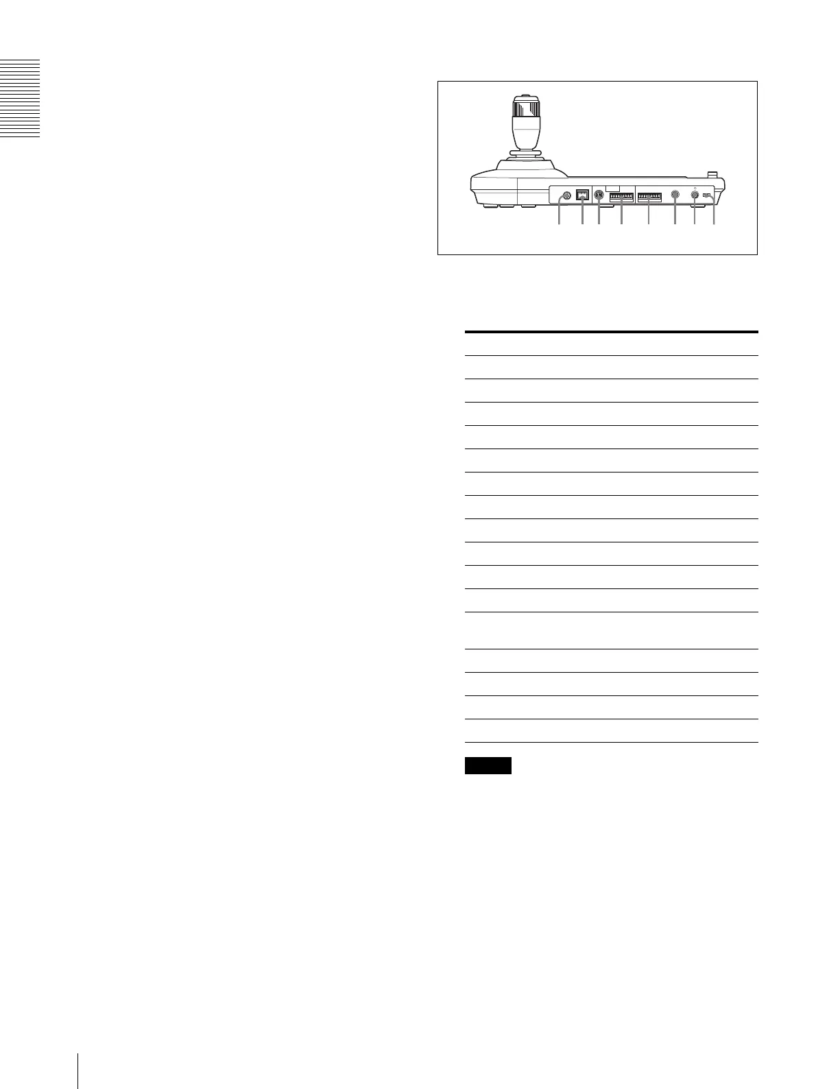
Rear
W MODE selector
Select the position corresponding to the camera to
be connected.
Note
Use positions 7 to 9, A, and B when all the
connected cameras are of the same model. In other
cases, use position 0.
X LAN connector (RJ-45 8-pin)
For LAN connection.
Connect a LAN HUB (10BASE-T/100BASE-TX),
using a LAN cable (category 5 or higher).
When a link is established, the green indicator
lights, and it flashes during communication. While
connected with 100BASE-TX, the yellow indicator
also lights.
Switch position Camera mode
0 Automatically selected (default)
1 Not used
2 Not used
3 Not used
4 Not used
5 Not used
6 Not used
7 BRC-Z700
8 BRC-Z330
9 BRC-H900
A BRC-X1000/H800/H780
B BRC-X400/X401, SRG-X400/
201M2/X120/HD1M2
C Not used
D Not used
E Not used
F Not used
MODE
VISCA
1919
RS-422
TALLY/CONTACT
RS-232C
!
DC 12V
LAN
f
g
h
j
k
l
d
;