5-54
A
H
A
H
White 100%
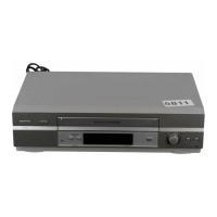
(4) C Signal Level Check (PAL)
Mode E-E
Signal Color bar (PAL) (VIDEO input)
Measuring Point Pin qg of CN003 (CL103)
Measuring Instrument Oscilloscope
Specified Value A = 600 ± 50 mVp-p
Switch setting:
INPUT SELECT switch.......................................VIDEO
NTSC/PAL switch...................................................PAL
Checking method:
1) Check the burst level (A) satisfies the specified value.
A
H
Fig. 5-3-11
4. Recording Signal Level Adjustment
(VD-031 Board)
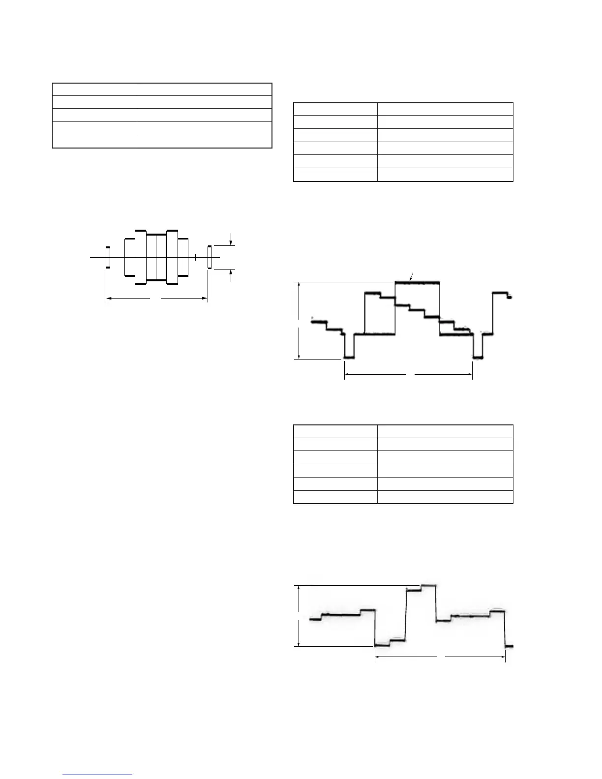
(1) REC Y Signal Level Adjustment (NTSC)
Mode E-E
Signal Color bar (NTSC) (S VIDEO input)
Measuring Point Emitter of Q126 (CL113)
Measuring Instrument Oscilloscope
Adjustment Element RV104
Specified Value A = 1.55 ± 0.05 Vp-p
Switch setting:
INPUT SELECT switch....................................S VIDEO
NTSC/PAL switch..............................................NTSC
Adjusting method:
1) Set the Y signal level (A) to the specified value using RV104.
Fig. 5-3-12
(2) REC CR Signal Level Adjustment (NTSC)
Mode E-E
Signal Color bar (NTSC) (S VIDEO input)
Measuring Point Emitter of Q118 (CL108)
Measuring Instrument Oscilloscope
Adjustment Element RV102
Specified Value A = 1.25 ± 0.02 Vp-p
Switch setting:
INPUT SELECT switch....................................S VIDEO
NTSC/PAL switch..............................................NTSC
Adjusting method:
1) Set the CR signal level (A) to the specified value using RV102.
Fig. 5-3-13
 Loading...